This thread has been locked.

If you have a related question, please click the "Ask a related question" button in the top right corner. The newly created question will be automatically linked to this question.

ADS5400-SP: PRBS test pattern in dual bus mode

Part Number: ADS5400-SP
Other Parts Discussed in Thread: ADS5400EVM

Hi,

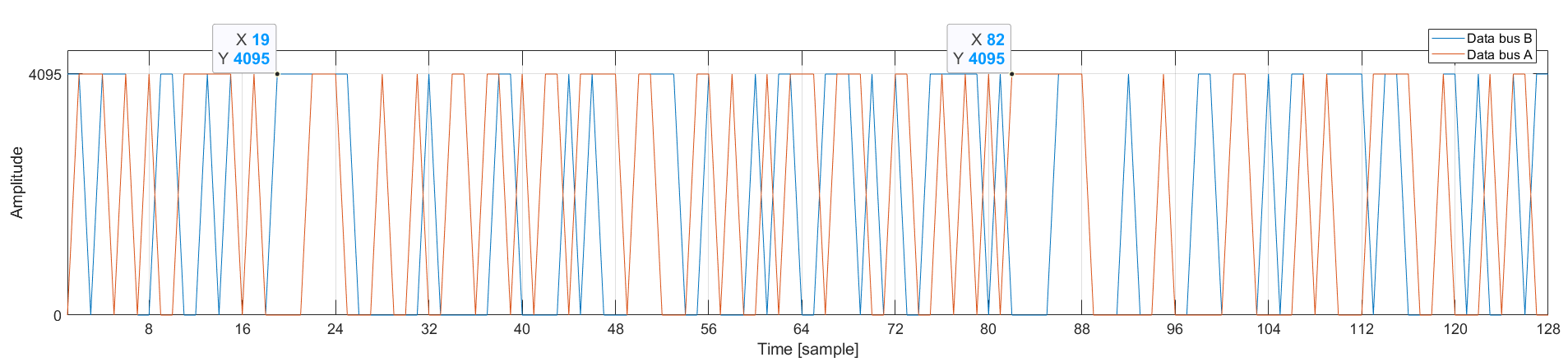
I am using ADS5400-SP in dual bus mode. In the PRBS output mode, should the outputs of data bus A and B always match? In our experiment, the phases of the PRBS7 sequence are not aligned at bus A and bus B. A misalignment of about 63 bits was observed.

Best regards,

  • Hi,

    There is a comment in the datasheet saying the start phase cannot be controlled in dual bus mode. It seems this is aimed at the toggle pattern only, but it is not totally clear. I will set this up and check it out, and will check back in early next week.

    Best regards,

    Drew

  • Hi,

    Apologies for the delay here. When you say there is a misalignment of 63 bits, does that refer to the spot in the 127-pattern sequence mentioned for PRBS, as this is only a 12 bit part?

    Regards,

    Drew

  • Hi, Drew-san,

    In the PRBS output mode,

    1. The data bus A always outputs 0x000 or 0xFFF.
    2. The data bus B always outputs 0x000 or 0xFFF.
    3. The output of data bus A is perfectly matched to PRBS7.
    4. The output of data bus B is perfectly matched to PRBS7.
    5. The phases of PRBS7 on data buses A and B are not synchronized. Is this as per specifications? The following figure shows our captured data.

    Thanks,

    Tomoya

  • Hi Tomoya-san,

    Are you using the ADS5400EVM & TSW1400EVM setup? Or are you collecting this data using your own FW?

    Keep in mind that the two separate busses should be collected and treated as a single data capture.

    On our lab bench setup, we collected bus A and bus B data and see these are perfectly matched. 

    Here is an example of the output data we collected. 

    Regards,

    Rob

  • Hi Rob-san,

    I am using my own boards and firmware. The reference PRBS7 I generated in MATLAB is as follows.

    1000000100000110000101000111100100010110011101010011111010000111000100100110110101101111011000110100101110111001100101010111111

    I finally understood that this PRBS7 is the same PRBS7 if I skip one by one. When data buses A and B are treated as a single data sequence, they match the reference PRBS7, and even when they are treated as independent data sequences, they each match the reference PRBS7.

    I have confirmed that my board and firmware work fine. Thank you so much!

    Regards,

    Tomoya