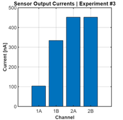
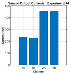
We are using the evaluation kit to develop an application where we need to measure negative currents. Following the guidance in the application note "CREATING A BIPOLAR INPUT RANGE FOR THE DDC112" we're introducing a large positive current to offset our expected negative current. During some of our tests we believe that our sensor current has transiently exceeded the positive offset. This appears to cause a difference between the A and B integrators as shown in the first chart. Only after putting the device into test mode do we agreement between the two integrators. As noted in a related thread the average of the two disparate readings is close to what is read after the reset. The device seems to work properly after doing the test mode reset but could a negative current damage the device?