This thread has been locked.

If you have a related question, please click the "Ask a related question" button in the top right corner. The newly created question will be automatically linked to this question.

ADC3643EVM: Isue with DCLK

Part Number: ADC3643EVM


Hi,

I'm currently trying to use an ADC3643EVM but when I check the DCLK output pin with an oscilloscope, this is what I see:


It's a very slow frequency signal, since the measurement is between -10ms and ~15ms.

Is there a problem with my card or is it just because I haven't configured it properly (I'm not configuring anything, just using the default configuration).
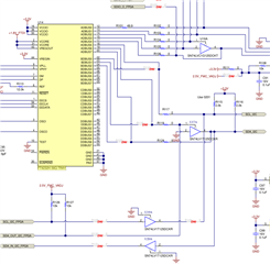
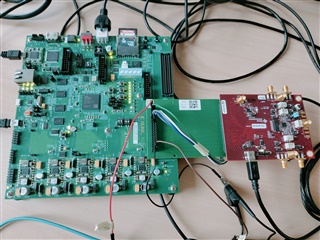
Here is my setup :

Thanks.

  • Hi Fabien, 

    You need to configure the part through the GUI and give a HW reset as well as enable the on-board clocking. 

    You can follow the steps outlined in the user's guide to get started: ADC364xEVM User's Guide

    Thanks!

    Cheers,

    Fadi

  • Hi Fadi,

    I don't have the TSW1400 card, which is why I didn't download the GUI.
    However, when I look at the user guide I see that the HW reset allows you to return to the default configuration. In this default configuration, shouldn't I have a correct clock signal? Because that's what I've done and I still get the same signal.

    Thanks

    Fabien

  • Thank you Fadi, the clock does indeed activate correctly as soon as the GUI is launched.
    However I would like to make it possible without launching the GUI, is this possible and if so what should I do?

    Fabien

  • Hi Fabien,

    This is because the on-board clock in the EVM is being turned on. You have two options:

    1. Using the on-board FTDI chip of the EVM to program the clocking device

    2. Modify the EVM board to accept external clocks for sample clock and DCLKIN

    Thanks!

    Cheers,
    Fadi

  • H Fadi,

    Thank you for this answer. What solution do you recommend?

    - If it's the FTDI solution, I need to add the resistors R128, R129, R130 and R131, is that all?

    And I'm not sure I have all the documentation on how to use this FTDI chip, do you have anything that can help me?

    - If it's the external clock, is it the DCLKIN_D3 that I need to use or the FPGA_CLK ?

    Thanks

    Fabien

  • Hi Fabien,

    The FTDI chip is already active, this is how the GUI communicates with the different ICs. The FTDI connects to USB and we bit bang I2C and SPI through it. 

    The resistors you pointed out would be for I2C only through the FPGA (from the FMC).

    The simplest solution will be to modify the board to accept external clocks. If you don't plan to use a serialized mode, then you only need to supply an external sample clock. You need to modify the below snippet to accept a single-ended or differential clock from the SMA connectors.

    Thanks!

    Cheers,
    Fadi

  • Hi Fadi,

    I use an fpga to control the ADC and I will use the parallel mode to transfert the data.

    I'm thinking of using this FPGA to generate the clock, which is why I was asking whether I should use the DCLKIN_D3 or FPGA_CLK input on the FMC connector. 

    Thanks,

    Fabien

  • Hi Fabien,

    If you want to use the FPGA clock, it looks like this board is only configured for singled-ended input clock from the FPGA. So you will need to modify the network accordingly.

    Additionally, you will need to set bit 0 of register 0X0E to enable SE-ended clock input. Thanks!

    Cheers,

    Fadi