This thread has been locked.

If you have a related question, please click the "Ask a related question" button in the top right corner. The newly created question will be automatically linked to this question.

ADS1278: Measurement drift with frequency

Part Number: ADS1278
Other Parts Discussed in Thread: INA828, OPA320

Hi,

We are injecting 300Vrms AC signal.  When changing input AC signal frequency from 40Hz to 60Hz  (without changing the input value)  we noticed that the ADC value RMS is changing

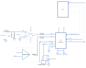
We are using INA 828 connected directly to ADS1278  as described below

Now note that the clock to the ADC is derived from the frequency of the signal so we can have 1024 samples in one cycle

What we see is that when the Fs is changing then the value read from ADC is changing as well

WHY???
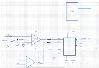
  • Hello Roman,

    Based on your simplified schematic, I think you may be seeing gain error.  The reference input and channel input both have an equivalent differential resistance, and this will create a gain error with the external 50ohm and 100ohm resistors in these paths.

    Based on the information you provided, it looks like you are using high-speed mode.

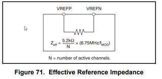
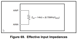
    At 40Hz input frequency, f-CLK=10.48576MHz.  The reference input resistance will be 13.4kOhm for each powered-up channel and the input resistance will be 36.0kOhm.

    At 60Hz input frequency, f-CLK=15.72864MHz.  The reference input resistance will be 8.9kOhm for each powered-up channel and the input resistance will be 24.0kOhm.

    Is the RMS value lower at 60Hz than at 40Hz?

    Regards,
    Keith Nicholas
    Precision ADC Applications

  • Hi,

    We are working at high speed mode indeed.

    we are aware of input impedance changes but we are facing increasing of RMS with frequency.

    Our injection is 300V

    60Hz -> higher voltage measured = 302V

    40Hz -> lover voltage measured = 299V

  • Hi

    We tried this configuration also but with the same results

    When Fs is 40 Hz the RMS value is lower then of 50Ha and higher at 60Hz

    We also tried short-circuit the 50 Ohms that are in series to the ADC but of no change ?!

  • Hello Roman,

    Since the calculated RMS value increases with increasing frequency, this suggests the reference voltage is reducing with increased frequency.  I do not see a buffer between the reference and the ADC REFP input, so this could be the source of the problem.

    Using a good DMM, I suggest you measure the voltages on the ADS1278 pins, AINP, AINN, and REFP.  If this is due to reference loading error, then you should be able to see a decrease in reference voltage of about 1%.

    If you can send a more detailed schematic, I could make some additional suggestions.  Specifically, what capacitor value is used at the ADC input pins?

    Regards,
    Keith

  • Hi Keith

    Thanks for your reply.

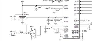
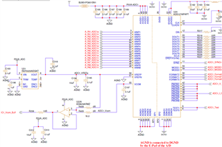
    Regarding the Reference Voltage it seems that there is no need to use a buffer as we implemented the scheme as it is in the application reference of the ADS1278 See below so we don’t think that the REFP input resistance is an issue

    Our implementation

    Regarding the testing of the voltages since it is a very low difference it is not practical to measure by the DMM

    The difference is in sub millivolts .

    In the AINP1 to AINN1 there is no capacitor in our design

    BTW even If the input resistance is changing from 36K Ohms to 24K Ohms between AINP and AINN it shouldn’t  have such an effect on the measurement

    Since the serial resistor is only 50 Ohms  as I indicated in the simplified scheme and we did also a test with the set=rial 50 Ohms resistors short-circuited but with no use The same drift of RMS vs frequency .?!

  • Hello Roman,

    Based on your previous data, the calculated reading is shifting by 1%.  If this is due to the reference, then you should see a 1% shift, or 25mV.  However, I agree this is not likely the cause based on your latest schematics.

    The input structure is a switched-capacitor load, that looks like an equivalent resistance when using an input 2.2nF capacitor.  Without the input capacitor, the output impedance of the INA828 and the VCOM buffers are likely much higher than 50ohm.  You should include a 2.2nF capacitor across each input channel; the capacitor will provide the high frequency current and the amplifier will supply the average current.

    Do you have all AINx inputs connected to the VCOM buffer?  Are all channels powered-up when doing these tests?  If yes, I suggest powering down all channels except for 1 and rerun your tests.  This should tell us if the VCOM buffer or the INA828 are contributing to the difference in readings between 40Hz and 60Hz measurements.

    Regards,
    Keith

  • Hi Keith

    Sorry , It took some time to response because we add the 2.2nf  capacitors to the input and it did actually improved the results We are now in the range of 0.1% 

    all  the AinN are connected to the VCOM buffer and all the channels are active during the test. What do you mean powering down"? Do you mean to disconnect the VCOM to the other channels of the ADC ? 
    This will cause these channels to go to saturation and to become noisy .

    One think that ew saw in the tests is that if we put a 1K resistor between the AinP and AGND then the results are stable ?I but now they are changing with the amplitude because of the 50 ohms in series that reduces the AINP by 0.5%  ( V *50/1K) :-( .

    Can you please send your suggestion of how to implement a direct connection of INA828 to the ADC1278 ? 
    thanks a lot 

    Roman

  • Hello Roman,

    Use the /PWDN pins to power down the channels; this will shut down the sampling on these channels, reducing both the average and dynamic current load on the VCOM buffer.  Looking at your schematic, I suggest taking measurements on channel 1 and power down channels 4-8.  This will reduce the load by 1/2 on the VCOM buffer.  If the VCOM buffer is contributing to the errors, you should see a difference in measurements.

    Regarding the INA828, looking at the suitability of this amplifier in more detail, it will not be able to directly drive the ADS1278 inputs and achieve the accuracy that I believe you are looking for.  In order to handle the high frequency currents from the switched input capacitor, a 2.2nF capacitor is required.  This capacitor acts as a charge reservoir for the high frequency currents.  Unfortunately, due to the limited bandwidth of the INA828, it can only drive this capacitor with about 1kohm or more of isolation resistance and have good stability.  This will create a large gain error with the ADC effective input resistance of about 14kOhm.  However, since you are adjusting the clock frequency of the ADS1278, this will directly change the input impedance, causing a change in gain error.  

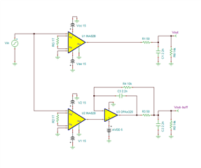
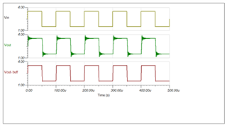
    For these reasons, I recommend adding a high speed buffer amplifier between the INA828 output and the ADS1278 input.  Below is an example circuit that shows how the INA828 responds with a small isolation resistor and the much improved response using the OPA320 buffer.  The OPA320 still requires a 50ohm isolation resistor to drive the 2.2nF capacitor.  This is normally acceptable because any gain errors can be calibrated, but in your use case, you are changing the clock frequency which also changes the effective input resistance, causing this gain error to change.  By using a dual feedback approach in the OPA320, the gain errors at lower input frequency, up to about 2kHz in this example, will be eliminated.

    Regards,
    Keith