This thread has been locked.

If you have a related question, please click the "Ask a related question" button in the top right corner. The newly created question will be automatically linked to this question.

ADS1178: ADS1178

Part Number: ADS1178

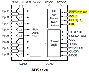
When interfacing the ADC bearing part number ADS1178 with controller, we are employing SPI lines to connect it to the controller. SPI entails connections for SCLK, MOSI, MISO, and CS. However, I would like confirmation on which pin of the ADS1178 module needs to be linked to the controller. Could you kindly confirm the specific pins that require connection?

  • Hello Asha,

    Welcome to the TI E2E community.

    The ADS1178 does not have a chip select (CS) input, and requires a dedicated SPI bus connection between the ADC and the MCU.  The ADS1178 continually converts data; there is no conversion start function.  The ADS1178 has a /DRDY output; the falling edge indicates that new data are ready to be read over the SPI bus.

    The MCU will need to monitor the /DRDY pin (either through software polling or an interrupt routine) to check for the falling edge.  Once the falling edge occurs, the data for the most recent conversion can be clocked out of the device over SPI.

    ADS1178 -> MCU:

    No connection -> /CS (do not connect /CS pin on MCU to any ADS1178 pin)

    SCLK -> SCLK

    DOUT1 -> MISO

    No connection -> MOSI (there are no internal registers inside the ADS1178)

    /DRDY -> General purpose input/Interrupt (data ready status)

    /SYNC - > General purpose output (should be pulsed after power-up or to reset device

    Other ADS1178 connections:

    DIN = 0 (Ground, only used for daisy-chain connection of multiple ADS1178 devices)

    DOUT[8:2] = no connection (all channel data will be sent over DOUT1)

    /PWDN[8:1] = 11111111b (IOVDD, all channels powered up)

    TEST[1:0] = 00b (ground)

    FORMAT[2:0] = 000b (configure for SPI, TDM, Dynamic)

    CLK = continuous oscillator from 100kHz to 27MHz, CMOS input referred to IOVDD

    CLKDIV = 1 or 0, see Table 4

    MODE = 1 or 0, see Table 5

    The above connections assume TDM mode over a single DOUT pin, in this case DOUT1.  In order to configure this mode, you can connect each of the FORMAT[2:0] pins to ground.  With all channels enabled (all /PWDN pins connected to IOVDD), each SPI frame will consist of 8*16 SCLKs, or 128 bits.

    Regards,
    Keith Nicholas
    Precision ADC Applications

  • For the ADS1178, MOSI and CS lines are unavailable. How can we establish an interface without these lines? Additionally, can alternative lines be utilized to connect to the MCU since we require four SPI lines? Can you please provide the answer.

  • Hello Asha,

    MOSI line is a no connect; does not need connected to anything since there are no internal registers inside the ADS1178.  There is also no /CS line and as a result, the ADS1178 requires a dedicated SPI port with no other devices connected to the SCLK and MISO lines.

    Regards,
    Keith