This thread has been locked.

If you have a related question, please click the "Ask a related question" button in the top right corner. The newly created question will be automatically linked to this question.

DAC8740H: Help with Loop-powered HART Receiver

Part Number: DAC8740H
Other Parts Discussed in Thread: DAC8742HEVM, DAC8742H

Hi,

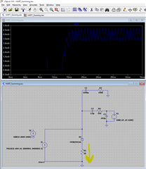
I'm designing a 4-20mA loop-powered receiver that also needs to communicate as a HART device.

Since I am powering off the loop, I'm planning on having a series of diodes to get a fixed voltage drop across the 4-20mA terminals. Something in the range of 6-8V. I'll then have a small sense resistor (10-50 ohm is what I'm planning) in order to read the analog input signal. 

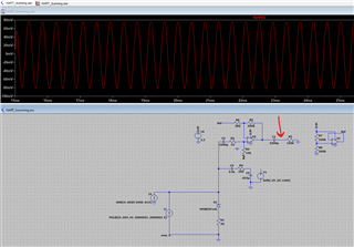
The issue that I'm trying to solve is how to make this work without a purely resistive input on the loop. Will tying the MOD_OUT and MOD_IN to the positive side of this diode network work? I don't anticipate any issue on the receiving portion but the transmission portion is where I have concern.

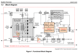
My input/power circuit will be similar in concept to this app note block diagram from TI:

Thoughts are appreciated!

-Brian

  • Hi Brian,

    We are reviewing this and will get back to you soon.

    Thanks,
    Lucas

  • Brian,


    Some of that may work, but there are some problems with what you are describing.

    First, I don't think the diode stack would be a problem. If you have current running through it, the diode stack would basically be at a constant voltage, while the resistive load would show the FSK signal as the current is modulated through the resistance.

    However, the resistive load would need to be amplified a little. The HART signal is a 1mApp sinusoid, so with a 10Ω resistance, that's 10mVpp. It would need to be capacitively coupled to a gain stage and then sent to the MOD_IN of the DAC8740H. The device receives a HART signal that is greater than 120mVpp.

    For transmission, you would need to create some sort of circuit to modulate the current through the loop. You can't just connect the MOD_OUT signal directly to the bottom of the resistor. If you look at the DAC8740H datasheet, you can see a schematic that combines a DAC output that sets the 4-20mA current and combines the modulated signal from the DAC8740H on page 34, Figure 35. The DAC output and the MOD_OUT are combined with a summing circuit. This circuit is for a transmitter, but I would guess that the receiver would be similar, and you'd need to set up a current source to pull the sinusoid current from the resistor.

    I'm not sure if this will help, but I did write an app note on the basics of the HART protocol. Here's a link for the note:

    https://www.ti.com/lit/an/slaaeh0/slaaeh0.pdf

    Joseph Wu

  • Joseph, 

    Thank you for your guidance. I think I would have missed amplifying the MOD_IN signal to 120mV for sure. 

    I put together a quick spice simulation of the transmission side (with some small differences than mentioned above) and I'm seeing the expected ~1mApp wave through the sense resistor. Using a resistor on the DAC8740 side of things. Am I missing something or would this setup work for the transmission side?

    Edit:

    I went ahead and simulated the MOD_IN side of things as well with a different simulation. If I amplify the input as shown, I'm seeing approximately +/-80mV (160mVpp) at what would be the input to the IC. I was a little unclear looking at the datasheet if the MOD_IN (Or should I be using MOD_INF in my case) could handle a negative voltage swing or if I need to offset that before entering the IC? 

    As always, I appreciate your help.

    -Brian

  • Brian,


    I think you can couple in a sinusoid just using an RC circuit, but it does seem a bit primitive to do it that way instead of using some sort of summing amplifier. I would definitely check the 2200Hz signal to make sure that it isn't further attenuated than the 1200Hz signal.

    For the sense signal going to MOD_IN, then input cannot take negative inputs. However, even in your schematic, this isn't a problem because the capacitance works to block the DC signal. I think it would be ok as well.

    If you want to test some of this, I would recommend getting the DAC8742HEVM (DAC8742H has a superset of features compared to the DAC8740H - mostly related to communication and register based functions).


    Joseph Wu

  • Joseph, 

    Thank you for your help. I'll definitely get one of the eval modules on order. 

    Can you help clear up what the MOD_IN input pin is looking for on the input? According to the datasheet, I see (pg9):

    HART MODEM

    MOD_IN INPUT (HART MODE)

    Input voltage range

    External reference source, specified by design. Signal applied at the input to the dc blocking capacitor. 0 to 1.5 VPP

    Internal reference source, specified by design. Signal applied at the input to the dc blocking capacitor. 0 to 1.5 VPP

    Receiver sensitivity Threshold for successful carrier detection and demodulation, assuming ideal sinusoidal input FSK signals with valid preamble using internal filter. 80 to 120 mVPP

    The 0 to 1.5Vpp is causing me some confusion. If you can clarify what it means I'd be very appreciative. 

    EDIT: 

    I guess while I'm asking, I have a similar question for the MOD_OUT signal. What does it really look like coming out of the chip? Is it a sinusoidal signal which is offset to make the bottom of the peak-peak waveform @ 0V? So, for example, a 450mVpp sinusoid with a 250mV offset?

    Thanks again!

    Brian 

  • Brian,


    For the MOD_IN input, the device is looking for a sinusoid signal. To receive it, the sinusoid can be as large as 1.5Vpp. I think it would have been more appropriate to use 80mVpp as a minimum instead of 0Vpp (which I don't think makes much sense).

    For the MOD_OUT signal, the output is a 450mVpp sinusoid. I think that this sinusoid is centered around 850mV dc above the device ground, so the bottom of the sinusoid is about 600mV above the device ground.


    Joseph Wu

  • Great! Thank you for your help with this.