This thread has been locked.

If you have a related question, please click the "Ask a related question" button in the top right corner. The newly created question will be automatically linked to this question.

ADS131E08: ADS131E08 stop in continuous mode after few minutes of running

Part Number: ADS131E08

We have configured the ADS131E08S based on the ADS131E0X datasheet . Subsequently,
we have read the ADS131E08S registers on the board using the ST-Link V2, and here are the details:


Readed ADS configuration regs :

1/ CONFIG 0 reg :

ID: ID Control Register

0x2d == 8 channel

2/ CONFIG 1 reg :

+ 0x91 (default): 16 bit resolution + 32 kbps data rate

1 0 0 1 0 001

+ 0x96 : 24 bit resolution + 1 kbps data rate

1 0 0 1 0 110

+ 0x92 : max speed : 24bit + 16 kbps data rate

1 0 0 1 0 010

----------------
3/ Config 2 reg :

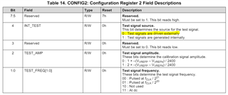
check value : 111 0 0 0 00 ==> signal amplitude. 0 : 1 × –(VVREFP – VVREFN) / 2400 ||| Test signal frequency. : Pulsed at fCLK / 2^21


4/ Config 3 reg :

0x60 = 0 1 1 0 0 0 0 0 ---> Power-down internal reference buffer + 4v vref + Noninverting input connected to the OPAMPP pin + Power-down op amp

-----------------------------

After the configuration of all configuration registers, and after checking and confirming that the register values are correct,
we have found that when we put the ADS in continuous mode, the ADS131E08S stops the conversion after some minutes.

is that a know issue ?

any idea about the cause ?.

best regards

  • Hi ziad jabbour,

    Can you provide more information as to the issue you are seeing?

    • Does the ADC always stop conversions after a few minutes, or can this issue occur after a few seconds, or not at all? In other words, is it randomly occurring, does it happen every time, or is it predictable?
    • If you try to restart conversions, does the ADC begin converting again? i.e. what actions do you take after the conversion stops? Do you need to power cycle, send the RESET command, etc.?
    • Are the register settings still valid, or did they reset?
    • Is any other surrounding circuitry affected when this occurs i.e. could this be a power-supply issue?
    • How do you know the ADC has stopped converting? Are you actually probing the SPI pins on the ADC and seeing that there is no more communication? If yes, what happens just before and just after the conversions stop on all of the SPI pins
    • Can you share a schematic?

    There is no obvious reason why the ADC would just stop converting after several minutes. So you will need to provide more explicit information about the failure mode before we can assist you further.

    -Bryan

  • Hi ,

    - The issue happen every time we set the Continuions Mode (0x10) and occur after a few seconds.

    - We have fixed this issue by putting the ADS131E08S IN discontinuions  mode(0x12) and a software reset.
     
    - Without the reset the communication with the ads is blocked and when we try to read the config registers , the returned values of the configs regs is 0x0 and the ads readed values :
               +  before the stop ==> values  correct for a few seconds 
               + after the stop ==> value  0 for the 8 channels

    Best Regards,
    Azer

  •  please fins as an attachment the schematics for the ADS interfaced with an STM32

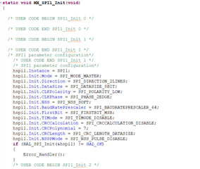
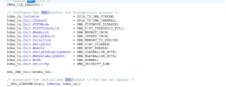
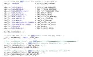
  • And this are the SPI and DMA configurations: 


    DMA:


  • Hi Azer khaled,

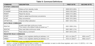
    I am not sure why this issue is occurring in your specific system, but I would always send the SDATAC command after startup so you can program the registers. See the highlighted sections below that state as such when you are in RDATAC mode.

    It sounds like you are able to get the device to work correctly in SDATAC mode using the RDATA command, is that true?

    -Bryan

  • Hello Bryan,

    Thank you for your response ,

    Yes , i was able to get the device to work correctly in SDATAC mode using the RDATA command

    Azer

  • Hi Azer khaled,

    Thanks for confirming, I would recommend using SDATAC mode then. It seems like this mode has resolved the issues you were experiencing.

    -Bryan

  • Hello Bryan,

    But the problem is that there is a software reset  is mandatory ,and if i don't reset it  the ADC will be blocked and due to this reset i m losing 20ms to reset the ads131e08.

    Moreover, even with the SDATAC mode and the software reset , the ads works fine only for 1 hour and then become blocked .

    Azer 

  • Hi Azer khaled,

    So you send an SDATAC command, then a RESET command, and everything works fine for about 1 hour - is that correct?

    Does the ADC always "become blocked" after 1 hour, or can it take longer / shorter? The title of this post mentions "minutes", while you mentioned "seconds" in a previous post

    And why does it take 20 ms to reset the ADC? The command is 8 SCLKs, followed by 18 tCLKs, which I assume is just a few microseconds total

    -Bryan

  • Hello Bryan,

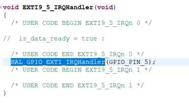
    I m sending the SDATA Command with interruption on (pin 5) like this : 

    interruption :

    read data : 


    and then in the callback i call the funct to Read the data of the 8 channels

    moreover , i m making software rest in the while(1) in the main function like this : 


    azer.

  • Hi Azer khaled,

    I am confused, you are using the "software reset" but you are toggling a pin to do so? Are you toggling the RESET pin? If so, that is a hardware reset

    Once the data is blocked:

    • If you try to restart conversions, does the ADC begin converting again? i.e. what actions do you take after the conversion stops? Do you need to power cycle, send the RESET command, etc.?
    • Are the register settings still valid, or did they reset?
    • How do you know the ADC has stopped converting? Are you actually probing the SPI pins on the ADC and seeing that there is no more communication? If yes, what happens just before and just after the conversions stop on all of the SPI pins?

    -Bryan

  • Hello Bryan,

    After each reset, the ADC begins converting again. However, if the ADS131E08 becomes blocked, I restart the board by cutting the power supply, initiating the cycle anew.

    If I don't perform the reset, the ADS131E08 works for 3 read cycles and then stops the read process, making no SPI communication possible with the ADS. Regarding the registers, before the blockage, the ADS131E08's registers are correctly filled, and the communication is good. Once the ADS becomes blocked, SPI communication with the ADS131E08 is no longer possible, and attempting to read any registers results in a returned value of 0x0.

    Azer


  • Hi Azer khaled,

    Do you get any response from the ADC once it is blocked? It sounds like you are getting 0x00 when you try to read registers. What about DRDY? Is this pin still pulsing at approximately 1/data rate when the ADC is blocked?

    If not, it sounds like you have some sort of power supply issue in your system. There is no obvious reason why the ADC would operate correctly for 1 hour and then suddenly stop working, requiring a complete power cycle.

    -Bryan

  • Hello Bryan thanks for your feedback 

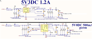
    the ADC is powered via this two blocks  with 500ma Capabilities, normally the ADC consumes less than 10mA

    do not hesitate if you have any comments 

    best regards

  • Hi ziad jabbour,

    Thanks for sending the power supply schematic. My point was that it seems like something is disrupting your power supply such that the ADC stops working i.e. this is not the fault of the ADC. If the ADC works for 1 hour, and then stops working, and then starts working again after a power cycle, then the ADC is not the problem

    As a result, I am not sure what additional support I can provide for you

    -Bryan

  • Hello Bryan,

    Once the ADC becomes blocked, the DRDY stops pulsing and no interruption is triggered.

    Best Regards,
    Azer

  • Hi Azer khaled,

    If the ADC stops producing DRDY pulses and is non-responsive to SPI communication (pending a power cycle), this means you have some sort of power supply or transient event occurring that is disrupting the ADC.

    -Bryan

  • Hello Bryan,

    I would like if you help me to verify the Software configuration and the main code if it's possible.

    here some detailes :

    Configuration and Issue Description for ADS131E08

    We have set up the ADS131E08 as detailed below:

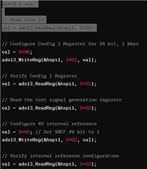
    1. Initialization and Configuration Setup:


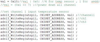
      Channel Configuration:


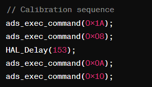
      Calibration Process:


      Issue: The ADS131E08 stops communicating over SPI in continuous mode after a few seconds without a reset. However, it operates in discontinuous mode with a hardware reset and delay. During this, either abnormal values are recorded, or it works continuously for approximately one hour before blocking SPI communication again.

      Could you provide insights or suggestions on resolving this issue where the device stops working in continuous mode? Any guidance on troubleshooting this behavior would be highly appreciated.


      best regards
  • Hi ,

    Could you provide insights or suggestions on resolving this issue where the device stops working in continuous mode or a C commands with Stm32 env ? Any guidance on troubleshooting this behavior would be highly appreciated.

    Best Regards,

    Azer.

  • Hi Azer khaled,

    The only way for us to verify your code is to see logic analyzer data of the digital communication. There are timing constraints associated with the commands you are sending, and we cannot verify those are met by just looking at the code

    Also, I will reiterate: whatever issue you are having does not appear to be an issue with the ADC. Our support will be very limited as a result of this because we are ADC experts, not experts with respect to your specific system.

    -Bryan

  • Hello Bryan 

    From my side the hardware side we did some verifications 

    to be noted we powered the ADC (TP23 on the attached schematics) via external lab power supply (5V) it did not change any things
    to be noted we used the evaluation board reference design ( ADS131E08) and we use the ADS131E08S
    WE measure stable voltages : on VREF = 4,05 / VCAP1 = 1,2V / Vcap2 = 2,5V / Vcap3 = 7V / Vcap 4 = 2V we use the internal clock and our SPI is at 8MHZ
    the only difference that i note in the ref design that we copied CAP1/CAP2/CAP3/CAP4 has much bigger values than the one recomanded in the datasheet 

    Cap1 recomanded 470pF we use 22UF as the evaluation board

    Cap2 recomanded 270nF we use 1uF as the evaluation board

    Cap3 recomanded 270nF we use 1uF as the evaluation board

    Cap4 recomanded 270nF we use 1uF  as the evaluation board

    VREFP Recommanded 330nF we use 10UF

    do you think this has any impact ? on start up time ? shall we modify the delays ??? 

    another difference that the input of the comparator is floating, but we do not use it and it is off by configuration

    maybe on the start time ? 

    please find as an attachment the schematics, the layout and the ref design that we used (https://www.ti.com/lit/ug/sbau200c/sbau200c.pdf?ts=1713285220311&ref_url=https%253A%252F%252Fwww.ti.com%252Ftool%252FADS131E08EVM-PDK)

    we measure very stable voltages on the board without any glitch 

    I am open to send you a bord sicne we are in a very bad position on the project and we need your help

    in case you think that it is a voltage glitch, can you help me where to measure it ? 

    once again thanks for your support

    Assembly-CoefH-Acc-A00.PDFSchema-CoefH-Acc-A00.PDFFABRICATION-CoefH-Acc-A00.PDF

  • Hello Bryan 

    hope you are doing well, and sorry for insisting, 

    do you see any blocking point on the schematics please ? 

    best regard

  • Hi ziad jabbour,

    Our goal is to try to resolve any issues with the ADC. But if the ADC runs as expected for 1 hour, then an issue occurs, but after a power cycle the ADC continues to run as expected, then I don't see that there is anything wrong with the ADC. It sounds like there is some sort of power glitch that is causing the ADC to latch up, but again, I don't know what could cause that within your specific system. There could also be multiple issues that are caused by each other

    The challenge with the problem you are experiencing is that there is no obvious cause. Therefore, I am not sure where to tell you to begin troubleshooting. There are basic steps like monitoring the power supply for any glitching behavior, replacing the power supply with a bench supply to rule out those issues, removing all the devices on your board to see if the problem stops and then slowly adding devices back to the board to see where the problem starts up again, testing your code on a known working board e.g. our EVM to make sure there are no code / timing issues, using our GUI with your board to check if your hardware is good, etc. But this is just basic troubleshooting, which you will have to carry out.

    As mentioned previously, the issue appears to be beyond the scope of the support we offer

    -Bryan

  • Hello Bryan 

    sorry for disturbing again, 

    If test (TestP & TestN) pins are pulled donw via 10K resistors, is that has an impact please ? 

    best regards

  • Hi ziad jabbour,

    See below for the relevant info from the datasheet about the TESTx signals.

    Note that by default the test signals are driven externally, which means you basically just have them grounded. If you are not using the test signals and have not changed the bits in the CONFIG2 registers, then this should not be an issue

    -Bryan

  • Hello Bryan 

    sorry for disturbing again, 

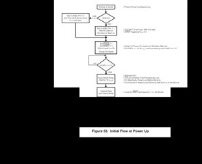
    I have strictly followed the datasheet specifications as well as the default modes of the ADC and its operation, and I conducted a test without performing a hardware reset, with the Start pin state maintained high, ensuring that the Ready pin state is triggered by a falling edge (falling edge interruption). Additionally, I kept the Power-Down signal at 1 and the clk is set to High, without sending any configuration data or commands to configure the ADC, all while keeping the CS pin at a low level, based on this flowchart from the ADS131E08 datasheet.


    1/ Can you confirm if, by keeping CS at a low level and keeping Start and Power-Down high, without sending configuration commands, the ADC automatically enters continuous mode and sends data on the SPI bus or not?

    2/ Is the CS signal linked to the Ready signal?

    3/ If not, by not configuring CS and keeping Start and Power-Down at high levels, can I still observe a change in the Ready signal?

    4/ Finally, there is a condition specified in the datasheet (page 28) called "signal is halted." Could you confirm if there are any other conditions that may cause the same behavior as "signal is halted"?

    5/ Could you please explain the right use and the mean of the DUT(annonced in the diagram attached below) and CLKSEL Pin 

    Best Regards
    Azer

  • Hi Azer khaled,

    Here are the answers to your questions:

    Can you confirm if, by keeping CS at a low level and keeping Start and Power-Down high, without sending configuration commands, the ADC automatically enters continuous mode and sends data on the SPI bus or not?

    The device does not send data unless you provide SCLKs. So if you are not sending SCLKs then no this will not occur. The DRDY signal should pulse at the default data rate, which is shown in the flow chart

    Is the CS signal linked to the Ready signal?

    By Ready signal, do you mean DRDY? If that is what you mean, then no, CS and DRDY are not linked

    If not, by not configuring CS and keeping Start and Power-Down at high levels, can I still observe a change in the Ready signal?

    Yes. This is explained clearly in the flow chart, see the second set of comments on the right

    Finally, there is a condition specified in the datasheet (page 28) called "signal is halted." Could you confirm if there are any other conditions that may cause the same behavior as "signal is halted"?

    Yes, if the device is in powerdown mode. Or if you turn off an external clock, or disable the power of course

    Could you please explain the right use and the mean of the DUT(annonced in the diagram attached below) and CLKSEL Pin 

    DUT = device under test. This is the ADS131E08 in the flow chart

    CLKSEL pin = clock select pin. This allows you to select between the internal or external clock. If you want to use an external clock, you will need to provide this signal to the ADC.

    -Bryan

  • Hi Bryan,

    Thanks for your respones ! 

    Could you please tell Me what is the minimal frequency and the Max Frequency of the SPI for the ADS131E08s ?

    One more question , could you please tell me is there any guidance for the clk and the frequency for the ADS131e08s that must be respected in the code and could cause this problem ?

    Best Regards,

    Azer 

  • Hi Azer khaled,

    The ADC clock specs are provided in Table 7.3 in the datasheet

    You must also follow all timing requirements as noted in Table 7.6 and Table 7.7. The SCLK frequency period is specified there as well

    If you don't meet the timing requirements in the datasheet the device might not work correctly

    -Bryan