Hi,
I'm trying to precisely understand the timings of the conversion of an ADS1220 related to the DRDY signal.
My starting point is the datasheet, "8.3.5 Output Data Rate" p.28 (SBAS501C revised August 2016).
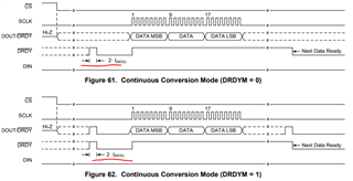
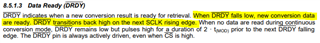
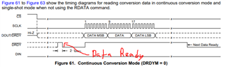
It is said that in normal mode continuous conversion mode, the first conversion starts 210*Tclk after the end of the SPI start message, but there is no mention of a delay between the end of a sample measurement and the DRDY signal, is it below Tclk?
Then for the normal mode single-shot mode, it is mentionned that the times (as Tclk) in table 11 are between the end of the SPI start message and the DRDY, but there is only a 98 Tclk (82Tclk for 20SPS) difference compared to the timings of the continuous conversion mode, which implies that the conversion starts faster for a single-shot compared to continuous mode?
Is it correct to assume that the actual time (during which the measurement is done) is the same between continous and single-shot, and that the 98 Tclk difference is the sum of before/after delays?
Thanks,
Étienne.