This thread has been locked.

If you have a related question, please click the "Ask a related question" button in the top right corner. The newly created question will be automatically linked to this question.

ADC12130: configuring the ADC 12138

Part Number: ADC12130

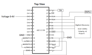
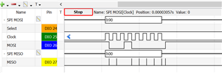
I am trying to configure the ADC12138 for single ended  , 12 bit , no sign , voltage measurement on channel 0 but unable to get the data on MISO line.

here is the sequence of instructions i am writing at DI pin.

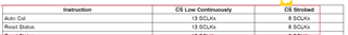
1. Write 0x08 Hex for Autocal. ( 8 bit word length since CS pin is strobed )

2. Write 0x0C Hex for reading the status register. ( 8 Bit word length ?)

3.Write 0x0C Hex again to confirm if  Autocal is completed or not. ( 8 Bit word length ?)

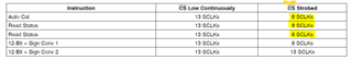
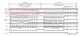
4.Write  0x0D Hex for  12 bit , " No sign " Data output format . ( not sure whether the Word length should be 8  or 12 ?  seems 8)

5.Write 0x80D Hex for channel 0 selection  to start the conversion. (not sure whether the Word length should be 8  or 12 ? )

6. Read  1 word of 12 bit data at DO pin.

the first question is if  the word length mentioned in brackets are correct for each instructions ?

second is if CCLK and SCLK pins are  shorted  then does it impact the Bit word length ?

looking forward to the answers / suggestions .

Thanks in advance .

  • Hi Rohan,

    Can you share your schematic and timing diagrams showing the commands you are sending to the ADC12138?

  • Hello Tom ,

    Please see below wiring diagram . 

    Pins CONV, PD, AGND, DGND VREF+/- ,COM connected to Ground.

    SCLK = 100Khz , CCLK = 5Mhz

    not using EOC signal .

    following commands are being sent 

    0x0A : Power up

    0x08: Autocal command

    wait for 1 secod for EOC

    0x09:Autozero command

    wait for 1 secod for EOC

    0x8D: Sign bit command

    wait for 1 secod for EOC

    0x0C: Read status

    0x0C: Read status

    wait for 1 secod for EOC

    0x90: Select channel 2 , single ended.

    Protocol.SPI.ReadWrite(8,[2])  ...reading two bytes of 8 bits data.

    is data on MISO line not sampling correctly ?

    any instruction is missing in the code ?

    SCLK and CCLK shoudl be shorted or have same frequency ?

    Please check and provide suggestions.

    Thanks

  • Hi Rohan,

    First - Vref+ needs to be something other than ground, usually it is going to be 4.096V as shown in Figure 63.  The conversion process uses the (stable, clean) reference voltage to compare against the voltage captured on the ADC input.  If the reference is 0V, the conversion results will always be 0.  I'll assume you have the ground pins of the Digilent tied to the same ground as your circuit.  SPI mode 0 is correct, so what do you see on the output after writing the Read Status command?

  • @Tom Hendrick , Vref+ is connected  to the +5V supply. grounds are tied to digilents ground .As datasheet says ,  Auto cal  command and then two Read status commands , you should see the status register data on MISO line. In the below image ,  the data  on MISO line is 00H for the same. 

  • Hi Rohan,

    Can you follow the sequence of Figure 62?  Send 12 to 16 clocks with the Read_Status and then see what get from the DO pin?

  • Hello Tom ,

    so all the configuration commands like Autocal, read status should be  sent with 16 clocks ? and the output data (12 bit , no sign)  to be sampled with 12 clocks ? 

    in datasheet , if the CS pin  is continously low then  it says to send 13 SCLK pulse ? 

    in figure 62 , 12 clock pulses are sent .

  • In Figure 62, the /CS is being strobed, the first sequence above (your red circle) is the command and the second frame (8 SCLKS) has the STATUS data.  Both frames can be 12 clocks wide for ease of use with your controller.

  • Hello Tom ,

     Autocal command ( once )  -> Read status command  (twice) -> channel selection command  (once) , and then  i should see the actual data on DO Pin . is that correct ?

  • Yes, I believe so.

  • And the output data to be sampled should be with 12 clock cycles i.e 12 bits of 1 word  ? with MSB bit first out ? 

    var c=Protocol.SPI.ReadWrite(12,[1])

  • is it necessary to send the channel selection command twice ? becuse i see 12bit +sign written twice ?

  • Correct - MSB can be first or last though

  • The second channel selection is for another channel, or another conversion on the same channel.

  • is it possible to get a sample code of initialization just to get kick started in this ?

  • Hi Rohan,

    Unfortunately we do not have any sample code to share with you.  I've ordered some sample units for myself and will try to get some detail for you.  It will take a few days though...

  • Looking forward to hear from you once you get the IC's . 

    I tried and  succeeded till getting status register values correct but the conversion data observed on DO pin was not correct and kept changing .