This thread has been locked.

If you have a related question, please click the "Ask a related question" button in the top right corner. The newly created question will be automatically linked to this question.

AMC131M03EVM: Questions about AMC131M03EVM-PDK-GUI

Part Number: AMC131M03EVM
Other Parts Discussed in Thread: AMC131M03

Hi

Testing amc131m03evm.
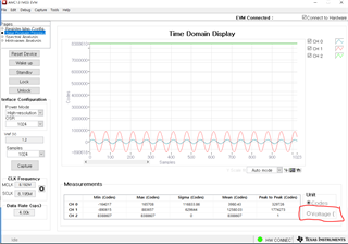
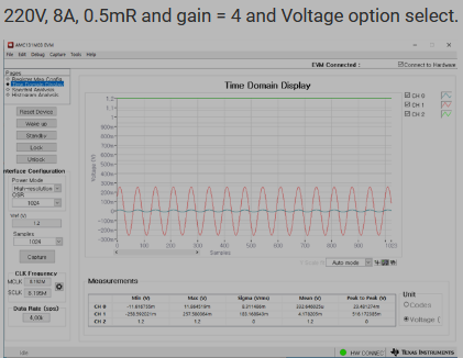
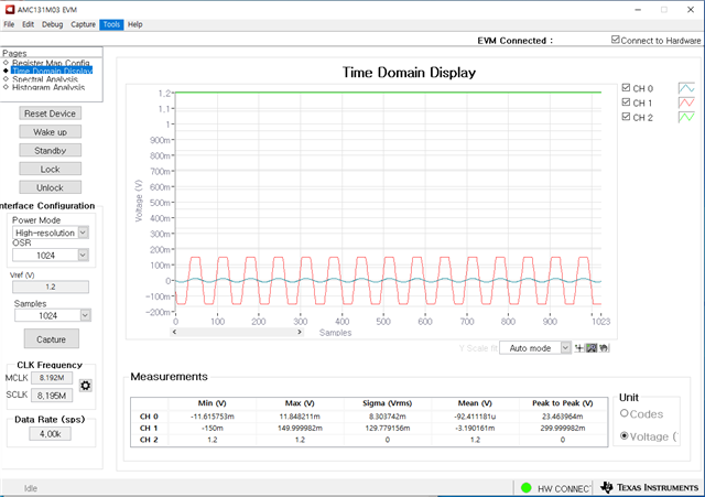
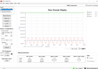
I don't know the meaning of the number among the GUI below.
How do I judge the numbers by looking at them?

Thanks

  • Hi David,

    Those numbers are referencing the ADC data code value.  The code value is directly related to the measured voltage value.  If your full-scale input range is FS and the output number of bits is n, the relationship between input voltage and the ADC output code is: Code_Value *(FS/2^n) = Voltage. There is also a setting under the Unit section that allows to view the measurements in voltage.

    Thanks.

  • Hi Saleh

    I don't understand gui's screen.
    The following 0a and 16a were compared and measured using an electronic loader at 110v.

     (110V 0A)

     (110V 16A)
    The code is changing and I don't know how to understand it.
    You gave me a formula, how can I calculate it? Can you give me one example?

    Thanks

  • Hello Saleh

    Q1 : Ch1, Peak to Peak values

    3622552 * (FS / 2^n ) = 220V

    What is FS values

    and What is 2^n values ?

    And Where can I find this values in the Datasheet document ?

    Q2 : Ch0 Peak to Peak value is 329726 (When a 110V 16A)

    How to calculation power current 

    *  clarification onething

    Avobe testing was used Default set and PC program.

    Regards

    ujack

  • Hi ujack/David,

    1. The FS value would be your full scale input range.  That is dependent on your gain setting for the device.

    The n value is the number of bits the measurement is.  This can also be configured.

    2. If the peak to peak adc value is 329726, the gain setting is 1, and the conversion data is set to 24 bits, you can calculate the peak to peak voltage as follows.

    329,726 * (2.4V/2^24) = 329,726 * (2.4/16,777,216) = 0.047V.  

    I'm not sure how this value relates to your system, since that depends on your circuit.  It would be proportional to your voltage when measuring through a voltage divider or proportional to your current if measuring across a shunt resistor.  To calculate total power, you would need both a voltage divider measurement and a shunt resistor measurement.

    Also,  you should be able to read the values in voltage by using the option circled in red below.

    Thanks.

  • First of all

    confusing me

    you comments : 329,726 * (2.4V/2^24) = 329,726 * (2.4/16,777,216) = 0.047V. 

    329,726 this number is CH0, CH0 is current and this number out from 110V/16A condition .

    so, recal -> 1774273 * 2.4V / 2^24 = 0.254V

    my testing 110V/16A but Cal result 0.254V, mismatched.

    my testing use your pc program and default set mode. - maybe this is GAIN =1 and 24Bit

    My question is simple

    How could I calculate ADC to Voltage and Currunt using CH1 for Voltage ADC and CH0 for current ADC

    Thanks

    ujack

  • Hi ujack,

    The measurement value is always going to be a voltage <1.2V. The voltage measurement will be related to your system voltage and current, based on the measurement circuit.  Would you be able to send me a schematic of your system?

    Thanks,

    Saleh

  • above means, is that 0.254V (-> 1774273 * 2.4V / 2^24 = 0.254V) 110V meaning ?

    if  input power 100Vac, what's the ADC number ?

    If input power 220Vac, What's the ADC number ??

    do you have calculation method ?

    my schematic is 

  • Hi ujack,

    Thanks for providing a schematic.

    Starting with the Voltage measurement:

    A few notations to help with the calculation:

    Vs = system voltage between 'RELAY_OUT_L' and 'RELAY_OUT_N'

    Vain1 = voltage between AIN1P and AIN12N, Channel 1 of AMC131M03 

    Co1 =  ADC code value for channel 1

    FSR = Full Scale Range of input to ADC, using Gain1 = 2.4V for calculation

    n = Number of bits from ADC conversion data, using 24 bits for calculation 

    The voltage divider between 'RELAY_OUT_L' and 'RELAY_OUT_N' is 750Ohm/900,750Ohm.  That will make the relationship between system voltage and the voltage reading from the AMC131: Vain1 = Vs*(750/900,750) -> Vs = Vain1*(900,750/750).  The relationship between the ADC conversion codes and ADC input measurement is: Vain1 = Co1*(FSR/2^n) = Co1*(2.4/2^24). Combining the two equations to solve for the system voltage we get:           Vs = Vain1*(900,750/750)  = Co1*(2.4/2^24) *(900,750/750).

    Using the ADC peak to peak code value from your image above (1,774,273), Vs comes to: Vs = Co1*(2.4/2^24) *(900,750/750) = 1,774,273*(2.4/2^24) *(900,750/750) = 305V peak to peak system voltage.  This would mean a 305/2/sqrt(2) ~=108V.  This seems close to your 110V, assuming the 110V is the rms voltage.

    For the current measurement:

    A few notations to help with the calculation:

    Is = system current flowing between 'RELAY_OUT_L' and 'TO_EV_CABLE_L1'

    Vain0 = voltage between AIN0P and AIN0N, Channel 0 of AMC131M03 

    Co0 =  ADC code value for channel 0

    FSR = Full Scale Range of input to ADC, using Gain1 = 2.4V for calculation

    n = Number of bits from ADC conversion data, using 24 bits for calculation 

    The shunt resistor value between channel 0 inputs is 0.25mOhms, which gives us: Vain0 = Is*0.25mOhms -> Is = Vain0/0.00025.  The relationship between the ADC conversion codes and ADC input measurement is still: Vain0 = Co0*(FSR/2^n) = Co0*(2.4/2^24).  Combining the two equations to solve for the system current we get:  Is = Vain0/0.00025 = Co0*(2.4/2^24)/0.00025.

     Using the ADC peak to peak code value from your image above (329,726), Is comes to: Is = Co0*(2.4/2^24)/0.00025 = = 329,726*(2.4/2^24)/0.00025 ~= 189A peak to peak.  This is pretty far from the 16A you mentioned, and I'm not sure why. 

    You can use the same equations to calculate the ADC code from known Voltage and Currents.

    One additional note:  For best resolution you will want to use the entire full scale input range. You can increase the gain to accomplish that.  

  • First Picture is 110V, 8A

    110V, 8A => CH0 : 157062

                         CH1 : 1794588

    Second P8icture is 220V, 8A

    220V, 8A => CH0 : 157360

                        CH1 : 3603936

    According to the your calculate, Result is, 

    110, 8A Graphic              
    ADC(CH0-전류) Gain=1 SCALE BIT Shunt R   Cal. Is I = Is/2
    157,062 2.40V 24bit 0.00050   Is = Vain0/0.5mR 44.9A 7.9A
              Is = Co0*(2.4/2^24)/0.0005    
              Vain=Is*shuntR    
    ADC(CH1-전압) Gain=1 SCALE BIT N line Resistor shunt R Cal. Voltage Vrms
    1,794,588 2.40V 24bit 900,000 750 Vs = Vain1*(900,750/750) 308V 109V
              Vs = Co1*(2.4/2^24) *(900,750/750)  


    220, 8A Graphic              
    ADC(CH0-전류) Gain=1 SCALE BIT Shunt R   Cal. Is I = Is/2
    157,360 2.40V 24bit 0.00050   Is = Vain0/0.5mR 45.0A 8A
              Is = Co0*(2.4/2^24)/0.0005    
              Vain=Is*shuntR    
    ADC(CH1-전압) Gain=1 SCALE BIT N line Resistor shunt R Cal. Voltage Vrms
    3,603,936 2.40V 24bit 900,000 750 Vs = Vain1*(900,750/750) 619V 219V
              Vs = Co1*(2.4/2^24) *(900,750/750)    

    Incase of I  - current - value >> 

    If divide the Is value by 2, that value becomes the actual current values.

    (Is / 2 / SQRT(2) / 2 = I current)

    Please let me know if there is any relation ??

    ujack

  • Hi ujack,

    Isn't your shunt R value 0.00025 Ohm because you have two 0.0005 Ohm resistors in parallel?  The shunt value of 0.00025 would bake the current value off by a factor of 4.  I'm not sure where this factor of 4 is coming from.  How do you know your system current is 8A?  Do you have another method to measure the current, or do you have high voltage probes to measure across the shunt?

    Also, could you try increasing the gain of channel 0?

    Thanks.

  • I'm sorry.. I'm not talk to you.

    above calculate and picture is used 0.5mR (not used dubule resistor) - new testing.

    8A : I used AC electric load equipment - Chroma 63804

    Increase gain : yes already control upto 128. if use 0.25mR shunt resistor, calculate result was wrong always. (not matched real and measurement values)

    but if use 0.5mR shunt resistor case is always correct current thru my method (Is / 2 / SQRT(2) / 2 = I current)

    So, I will ask again.. What is the connection? Is it something completely different? Is this a ridiculous calculation method??

    give us your opinion..

    (you : shunt value of 0.00025 would bake the current value off by a factor of 4.)

    (redaction: The shunt value of 0.0005 would bake the current value off by a factor of 4.)

    ujack

  • Hi ujack,

    Increase gain : yes already control upto 128. if use 0.25mR shunt resistor, calculate result was wrong always. (not matched real and measurement values)

    When you increased the gain, was the error factor the same?

    So, I will ask again.. What is the connection? Is it something completely different? Is this a ridiculous calculation method??

    I'm not sure what is causing the current measurement to be wrong.  The calculation method from ADC code to current should be correct.  Have you tried using the voltage view in the GUI?

    What shunt resistor are you using?  Can you send me the layout of the board?  Do you have another method to verify the current, something like differential high voltage probes to measure across the shunt?

    Thanks

  • if I used 0.25mR shunt gesistor, Current and Voltage values was wrong, even controled Gain. so, I want to forget about 0.25mR issues.

    Only focus on the 0.5mR shunt resistor using case. 

    I used AC load equiment and check alredy thru AC current meter as below photo 


    You are wondering about GAIN control result. and selected Voltage option.

    below picture is 

    220V, 8A, 0.5mR and gain = 4 and Voltage option select.

    and next is 

    220V, 8A, 0.5mR and gain = 8 and Voltage option select.

    * I don't know how to calculate Voltage and current, anyhow result values was wrong 

    * and question, in case of Gain =8 picture, Voltage is not sine wave. I think, is this saturation ?

    (if try to 110V input : upto gain =8 is OK, but after gain=16, distortion occurs in the sine wave)

    * gain=4 and gain = 8, current value was almost same (8A condition)

    I can send layout PCB but if I send, I need expain more and you get a confusing.

    Because now first PCB, so not completed, I have many jumper wires

    Anyhow I will attached PCB screen chapture.

    we connected SPI line to TI EVM KIT (for monitoring by PC) and we use power thru our own PCB.

    ujack

  • Hi ujack,

    I'm not sure why, but I'm not able to view the pictures you sent.  Can you please re-send them.

    Also,  can you try a higher resistance shunt for debug purposes, maybe something around 10mOhms?  I'm worried that the shunt connection between the device inputs might have some extra resistance either from trace or soldering.

    Thanks.

  • Thanks Saleh.. 

    picture send again 


    => OK I will do that but need take time for test and  let you know the results

    => In the meantime, take a look at why I got this result values and wave distortion.

    ujack.

  • Hi ujack

    * and question, in case of Gain =8 picture, Voltage is not sine wave. I think, is this saturation ?

    Yes this is because of the saturation on the input side of the device.  Depending on the gain selected the input voltage range of the device changes.  For a gain of 8, the input saturates at +-150mV.

    I don't know how to calculate Voltage and current, anyhow result values was wrong

    When the 'unit' is set to 'voltage' in the GUI it will read out the voltage measured on the input.  The calculation between the adc code and that voltage is Vain1 = Co1*(FSR/2^n).  From there you can calculate the system voltage and current using Vain1 = Vs*(750/900,750) and Is = Vain0/0.0005. 

    Could you send me a picture of your setup, specifically where the shunt resistor is?

    Thanks.