This thread has been locked.

If you have a related question, please click the "Ask a related question" button in the top right corner. The newly created question will be automatically linked to this question.

DAC61402EVM: DAC61402EVM

Part Number: DAC61402EVM
Other Parts Discussed in Thread: DAC61402

Hi,

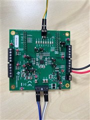
We are planning to use DAC61402EVM. As per the user guide, the Eval board expects to be configured with a MSP LaunchPad. We have below questions:

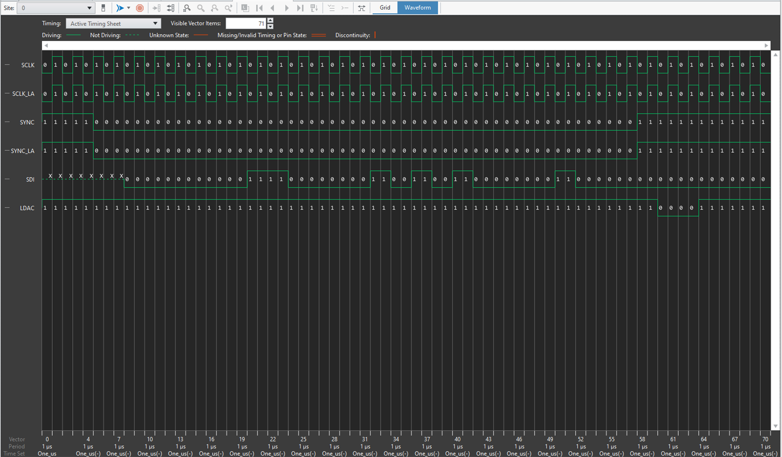
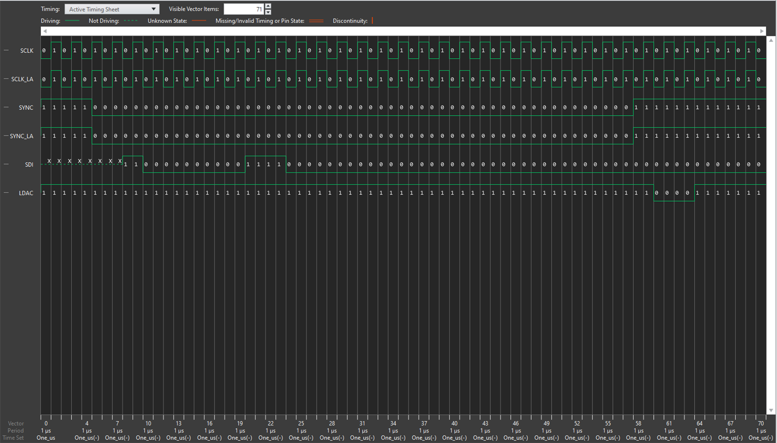
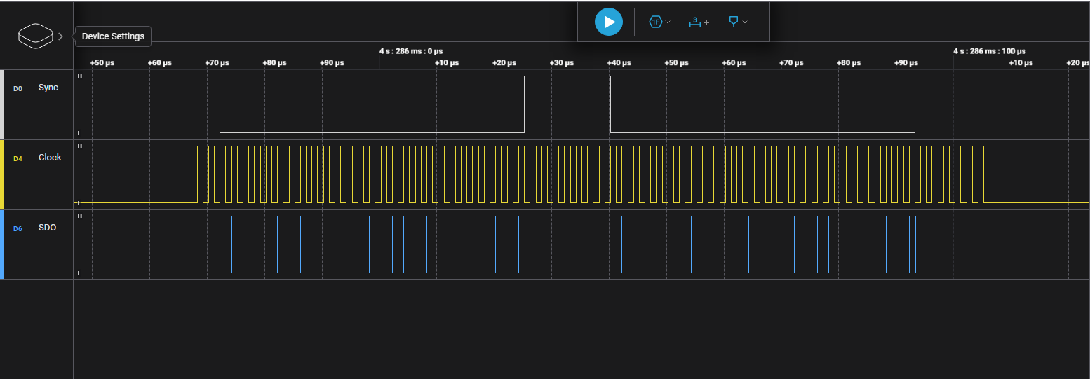
1) Can we connect external digital signals(SPI) and test the board,

2) Is connecting with LaunchPad mandatory to start-up the DAC board working?

3)  If DAC board is configured once with Launchpad at power up, can the connection be removed and use the DAC board as standalone board? 

Let me know for more inputs.

  • Hi Kiran,

    1) Yes, any external SPI controller can be wired directly to the SPI pins on the EVM. 

    2) No, not mandatory. 

    3) If the DAC is power cycled, the device will lose the register settings that you previously configured with the external SPI controller or Launchpad because there is no memory on this device. If you remove the Launchpad while maintaining power to the device the DAC will remain at the output voltage that you previously configured. 

    Best,

    Katlynne Jones 

  • Hi Katlynne,

    1) We are trying to communicate with DAC61402EVM and referring to the procedure mentioned in User Guide, but the BP-DAC61402EVM folder is not present in GUI composer gallery, could you share us the required folder to communicate with Launch pad.

    2) We also tried to communicate with DAC61402EVM as standalone (not connected to Launchpad), but we have not observed output from DAC. We have provided power externally (DVDD, AVDD, IOVDD). We tried the following sequence:

    - Write 0xE (Address), 0xA (Data)

    - Write 0x4 (Address), 0x0 (Data)

    - Write 0x9 (Address), 0x0 (Data)

    - Write 0x11 (Address), 0x7D0 (Data - code equivalent to 2000)

    Let us know for more input.

  • Hi Kiran, 

    Sanjay is reviewing this and will provide an answer shortly. In the mean time, it might also be helpful to know how you have configured the EVM. What are the jumper configurations you have used and what supplies do you have connected in both cases. You can take a picture of the EVM and share it here. 

    Best,

    Katlynne Jones

  • Hi Kiran,

    As Katlynne pointed out please share EVM configuration and supply values.
     

    And if you are trying to communicate standalone mode please use the write sequence mentioned below to get proper DAC output-
     

    1. Write 0x0A84 in SPICONFIG (0x03)

    2. Write 0x0000 in GENCONFIG (0x04)

    3. Write 0x0000 in DACPWDN (0x09)

    4. Write 0xFFFF in DACA (0x11)

    You should get 5V on DACA output.

     
    Thanks,

    Sanjay

  • Hi Sanjay,

    Thanks, please find below screenshot of EVM configurations for standalone and we have given 5V at 3 places externally (AVDD, DVDD, IOVDD). And reading output from channel A on DMM.

    Let me know for more inputs.

  • Hi Kiran,


    This supply connection looks to be okay. 

    Follow the datasheet and EVM's user guide for proper digital connection and DAC VSENSEP/SENSEN connection. 
     

    and after that provide these details - 

    a. supply values of AVDD, AVSS, DVDD and IOVDD with respect to any GND pin.

    b. try to communicate in standalone mode and use the write sequence mentioned below and measure the DACA output-
     

    1. Write 0x0A84 in SPICONFIG (0x03)

    2. Write 0x0000 in GENCONFIG (0x04)

    3. Write 0x0000 in DACPWDN (0x09)

    4. Write 0xFFFF in DACA (0x11)


    You should get 5V on DACA output and 2.5V on TP11 (DAC_REF).

     
    Thanks,

    Sanjay

  • Hi Sanjay,

    Thanks for the commands.

    We are trying to read back the register values using commands on SDO line, first we sent 0x030A84 on SDI line. then we sent 0x830000 on SDI line so that we could read back the values of 03 register, but we are not getting expected values. please find below images for same.

    -> Writing 0xA84 to 03

    -> Writing 0x830000 (for reading register 3)

    -> Captured SDO, SYNC and SCLK on logic analyzer

  • Hi Kiran,


    Your SPI frame is not correct and has following issue - 

    1. Number of clocks are more than 24 (=~26) - not okay 
    2. Your SDIN data is not latching on the clock falling edge, it's on the clock rise edge - not okay

    For DAC61402, SPI frame should have only 24 clocks and SDIN data should be latched/clocked on falling edge of SCLK line.

    Please read the detailed explanation from the DAC61402 data-sheet about the timing requirements in the sections mentioned below - 

    7.12 Timing Diagrams

    8.5 Programming >> 8.5.1 Stand-Alone Operation


    Thanks,

    Sanjay

  • Hi,

    Let us know if we could schedule a call this week Thursday or Friday.

  • Hi Kiran,

    Sure.
    Let's meet on Monday 03/06 around 11:30AM Bangalore (IST) time. I have dropped a mail on your registered email address for the same. 

    Thanks,

    Sanjay

  • Hi Sanjay,

    As discussed, the DAC output A corresponds to output B on DAC61402EVM. Also, the Device ID read is 0920h.