Hi Team,
Customer is asking if we have any example register initialization software code for AFE5809 for reference, can you help to check and provide it?
Thanks.
This thread has been locked.
If you have a related question, please click the "Ask a related question" button in the top right corner. The newly created question will be automatically linked to this question.
Hi Team,
Customer is asking if we have any example register initialization software code for AFE5809 for reference, can you help to check and provide it?
Thanks.
Hi,
If they are not using demod nothing needs to be written as a initial configuration. ADC output format and resolution needs to be set according to customer use case .
What is the condition they are looking for ?
The provided Python code snippet demonstrates register initialization for an Analog front-end (AFE) device. Utilizing the smbus2 library, at and t internet plans it establishes communication via the I2C bus with the device at address 0x48. Subsequently, it writes predefined register data to configure the AFE device. This process ensures proper initialization, facilitating subsequent operations and interactions with the AFE within the system.
I am not able to open the link you provided . But what was your query ? This device follows spi protocol. What do you mean by device in " it establishes communication via the I2C bus with the device at address 0x48 "
Hi Sachin,
Customer would like to use below functions for AFE5809, can you help to generate the example configuration code as reference? We don't have EVM for this device in hand, so can not use GUI to generate scripts.
(1)Will use demod, enable decimation and low pass filtering, decimation=4, low pass filter 5MHz.
(2)before demod, ADC resolution is 14bit, after I/Q, data resolution is 16bit.
(3)Need I/Q data sync with channel clocks.
(4)need to remove DC for received signals.
Other registers can be default.
Thanks a lot!
Hi Sachin,
Can you kindly help to give us some example configuration code for above requirements?
Also, customer has below questions when using AFE5809, please help to check:
(1)
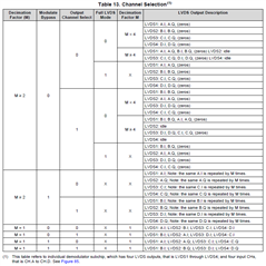
Customer has make the configuration according AFE5809 datasheet table 13, but can not get the correct output I/Q data format, please help to suggest what's the possible reason?

(2)After the received signal is demodulated and filtered, the spectrum is analyzed and it is found that a DC signal with a strong signal appears, which needs to be removed. It would be best to provide a configuration demo of the demodulation module for reference.
(3)The output IQ data should be aligned with each channel clock. In addition, the signal clocks between the three boards should be aligned synchronously.
(4)There is a problem with the setting of the demodulation frequency. The result of using 10M demodulation for 10M transmission does not seem to be as expected and not quite right.
Thanks.
Down conversion is enabled or disabled ? If enabled what is the down conversion frequency ?
I assume they want to enable as they are asking I/Q data.
1) What are they observing ?
2) We can use dc removal register setting to remove DC
3) Using TX_TRIG we can align data from different device
4) What is clock frequency and what is demodulation frequency?