Other Parts Discussed in Thread: USB-TO-GPIO2,
Hello.,
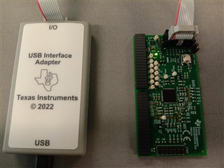
With the USB-to-GPIO2 adapter and the UCD3138 components in hand, what's the process for flashing the firmware onto the UCD? Is it possible to do so without an XDS110 adapter?
Hello.,
With the USB-to-GPIO2 adapter and the UCD3138 components in hand, what's the process for flashing the firmware onto the UCD? Is it possible to do so without an XDS110 adapter?