This thread has been locked.

If you have a related question, please click the "Ask a related question" button in the top right corner. The newly created question will be automatically linked to this question.

ADS7066: Auto Sequence Mode Reading data frame size? 12bit? 16bit?

Part Number: ADS7066
Other Parts Discussed in Thread: ADS7067

Hi, I have the same question.

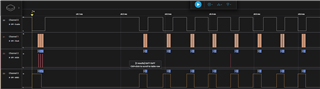
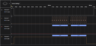
When I set the ADS7067 to Auto sequence mode, set the "SEQ_START" bit to 1,

and set "AUTO_SEQ_CH_SEL" TO 0X00(all 7 channels set to Analog in); 

I can't get  any data from all 7 channels, it's always 0xFF.

Datasheet Chapter 7.4.4 suggests the output data format of SDO should be 16 bit or 20 bit,

but Table 7-15  shows that SDO should  only has 12 clocks, even it is a 16bit ADC.

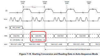
So what exactly is the auto-sequence reading command?

  • Hello Joe,

    Thank you for your post.

    To select a channel for Auto Sequence mode, the appropriate bit in the AUTO_SEQ_CH_SEL register must be set to 1b. Writing 0x00 to address 12h will disable all channels.

    Regards,

    Ryan

  • Ryan, thank you for your reply!

    Sorry, I  typed the wrong register name;

    I meant  I set the register "PIN_CFG" to 0X00 (config all 7 channels to Analog in), 

    and set "AUTO_SEQ_CH_SEL"  to 0XFF (all 7 channels enabled in scanning sequence).

    I also set the SEQ_MODE of "SEQUENCE_CFG" to 01b ( Select Auto Sequence mode),

    and set the" SEQ_START" bit of  "SEQUENCE_CFG" to 1b (start channel sequencing ) just before

    reading ADC values by transmitting 8 data frames of 16bit low (0x00,0x00) on SDI.

    Besides,   I disable averaging filter, input/output CRC,  and Channel ID/ Status Flag,

    so that the data frame size is 16  bits.

    But I still  get  wrong ADC readings.

    Is there still anything  I missed? 

  • Hi Joe,

    Thanks for clarifying. Those register settings and the initialization sequence look correct. 

    Referring to Table 7-4, you may still need to send 24 SCLKs, even though CRC, averaging, and STATUS words are all disabled. Can you try extending the frame to send 3 bytes of 0x00 on SDI? I might also recommend enabling the channel ID status just for now to ensure that the internal multiplexer is cycling through the channels as expected.

    Can you share a schematic so we can review what all is connected to the I/O lines?

    Regards,

    Ryan

  • Hi Ryan,

    I figure it out!

    My register settings are all correct, and the 16bit 0x00 command also works.

    The real issue is that I can't distinguish which data frame corresponds to which channel since I did not append the 4-bit Channel ID to the data frame.

    That's why I thought I had read a wrong value.

    Besides, I think the term "12 clocks" shown in Table 7-15 actually means "Read 12-bit data and discard it. ", which is not mentioned in the datasheet. 

    This 12-bit  data was also misidentified as a reading from one of the eight channels.

    Therefore, I followed your advice to send 3 bytes of 0x00, and enable the 4-bit Channel ID.  

    Read and discard the 12-bit data just after setting "SEQ_START" bit to 1. 

    Now all 8 channels' readings are correct.

    Thank you!

  • Hi Joe,

    Thanks for the feedback and I'm glad you figured it out! This is really helpful to know. I'll submit the feedback to our systems team so that it may be included in the next data sheet revision.

    Best regards,

    Ryan