This thread has been locked.

If you have a related question, please click the "Ask a related question" button in the top right corner. The newly created question will be automatically linked to this question.

ADS1278: SPI configuration

Part Number: ADS1278

HI team ,

     I am Working in the project of data acquisition system so we need 8 channel input in this case we choose the ADS1278. To configer the ADS1278 through the SPI protocol,

we are configer the  configeration through the I/O pins 

ADS1278 Input Pin -TEST pin[0:1]  //this pins are set to LOW Because we use Normal Mode.

ADS1278 Input Pin -FORMAT pin[0:2]    // this pins are set to LOW Because we use SPI TDM Dynamic formate.

ADS1278 Input Pin -MODE pin[0:1]  //this pins are set to LOW Because we use High-Speed Mode.

ADS1278 Input Pin -POWER DOWN pin[0:8]  //this pins are set to HIGH Because we use 8 Channel of input.

ADS1278 Input Pin -CLKDIV pin 1  //this pins are set to HIGH Because we need Higher sample per Second.

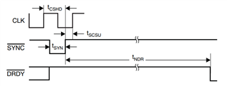
ADS1278 Input Pin -CHIP SELECT/SYNC pin 1  //this pins are set to HIGH OR LOW(Based on the condition).

ADS1278 Output Pin -DRDY pin 1  //Read the pin.

FCLK=25MHz

SCLK=25MHz

After the configeration 

First CHIP SELECT/SYNC pin put low

After monitering the DRDY pin //When the pin is Low ....Move the next condition.

In spi write 24 Bytes data=0 will send / Also 24 Bytes of SCLK will also send.

But SPI Read function there is no data is recived 

CHIP SELECT/SYNC pin put HIGH...... In this time DRDY pin is gose to High

HOW to Retrieve the data....?

Please give me a reference code.

Thanks and Regards,

Aravind.SR

  • Hello Aravind,

    Your setup looks correct, except for the use of the /SYNC pin.  SYNC functions similar to a RESET; when low, the device is in a RESET state and no conversions take place.  When SYNC is taken high, there will be a delay before the first conversion data is ready, indicated by the falling edge of /DRDY.  Figure 73 in the datasheet shows the behavior of /SYNC and /DRDY.  The delay time before the first conversion result after /SYNC rising edge is tNDR, which is equal to 129 conversion periods.  In your case, since CLK=25MHz (I assume you have a 25MHz continuous clock connected to the CLK pin 27), then a conversion period will be 1/25MHz*256=10.24us.  tNDR=129*10.24=1.32 milliseconds.

    After /SYNC pin is taken high and tNDR time has been met, the /DRDY pin will pulse at the output data rate.  In your configuration, this will be 97.656ksps.  Your processor needs to either poll the /DRDY pin or monitor with an interrupt, and look for the /DRDY falling edge.  At this time, you can then clock the data using SCLK out of the device.

    If you do not see any activity on the /DRDY pin, then you have a hardware problem.  I suggest checking all supply voltages, and verify you have a continuous 25MHz clock present on the CLK pin.  The voltage levels of this clock should be equal to the IOVDD supply voltage.

    Regards,
    Keith Nicholas
    Precision ADC Applications