This thread has been locked.

If you have a related question, please click the "Ask a related question" button in the top right corner. The newly created question will be automatically linked to this question.

ADS1299: 50Hz noise observations

Part Number: ADS1299

Hello,

I have to develop a system for EMG acquisition, I am using the ADS1299EEG FE Rev A evaluation board. My reference electrode is placed between the signal electrodes, about 10 mm of distance between one electrode and the other.  In order to better understand how the system works, I would like to ask you some questions:

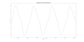
  1. Why does the noise signal that I catch have a DC component? Could you explain the physical reason for this (any model, paper, phenomenological motivation)? If I short the input pin (internally or externally), I measure correctly the expected offset relatively to the gain that I am using.
    Sometime I observe also a drift of the signal. 


2. Why if the reference electrode is connected to GND, the signal is clipped? Something with the bias current on INxP and/or INxN of the low noise PGA?

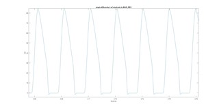
register values: from 0x0 to 0x17

{0x3E, 0x93, 0xC0, 0xEC, 0x00, 0x00, 0xE1, 0xE1, 0xE1, 0xE1, 0xE1,
 0xE1, 0xE1, 0b00000000, 0b00000000, 0x00, 0x00, 0x00, 0x00, 0x00, 0x00,
 0x00, 0x00, 0x00};


thank you

  • Hi Damiano - please excuse our delay. Do you still need help with this?

    Regards,

    Ryan

  • Hi Ryan,

    yes, I still need your help.

    About question 1, I have no idea, so if you can give me also some explanations or references, I will appreciate a lot.


    About question 2, the reason could be a difference in the GND of my own body respect that of the acquisition system? When this GNDs are connected in a DC way, could happen that the signal read is negative respect this GND and the ADS1299 clips the signal on its low limit?

  • Hi Damiano,

    1. The offset voltage you observe is caused by leakage current on the input pins and the impedances in the signal path. Neither the leakage current or circuit impedance will be perfectly matched due to drift, electrode impedance mismatch, PCB parasitics, etc. Some offset calibration or digital filtering would be necessary in order to remove it from the measurement. Generally, a few millivolts of offset is not an issue since the signals of interest are AC.
    2. The BIAS electrode should be used to establish a mid-supply common-mode voltage on the body equal to (AVDD+AVSS)/2. The voltage on each input pin is limited by the supply voltage.

    We have quite a few resources on ECG applications in our BIOFAQ E2E page. Many of the topics are applicable to EEG as well.

    https://e2e.ti.com/support/data-converters/f/73/t/772058

    https://www.ti.com/video/5423179600001

    Regards,

    Ryan