This thread has been locked.

If you have a related question, please click the "Ask a related question" button in the top right corner. The newly created question will be automatically linked to this question.

ADS1299EEGFE-PDK: ADS1299EEGFE-PDK

Part Number: ADS1299EEGFE-PDK
Other Parts Discussed in Thread: ADS1299,

1. I want to check the device registers through spi and computer software at the same time, so I use ads1299 spi to connect to Arduino, and mmbo+ads1299EEGFE-PDK to connect to the computer.
I want to know if it is possible?


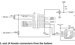
2. Are these the connections on the ADS1299EEGFE-PDK top face SPI (as shown below)?

1,6,8,11,12,13,16,19,20=na

2=EXT_CLK

3=DRDY

4=DOUT

5=DIN

7=CS

9=SCLK

10=CLKSET

14=START

15=GPIO2

17=RESET

18=GPIO1

I didn't see this section in the User's Guide so wanted to confirm.

  • Hello Chen,

    Thank you for your post.

    Our support for the EVM-PDK is limited to using the provided hardware and software as-is. We cannot guarantee the communication between the EVM and the MMB0 motherboard will not be affected by the Arduino when they both share the SPI bus.

    The J3 header connections are detailed in the schematic of the ADS1299EEGFE-PDK User Guide. The silkscreen appears to have mislabeled the CLKSEL pin on the PCB, so please following the connections detailed in the schematic:

    Regards,

    Ryan

  • Thanks for the reply Ryan
    I understand the pins on the Pcb.

    I want to use MMB0 to provide power (in the case of a combination of the two MMB0+ADS1299EEGFE-PDK), so as long as I don't connect MMB0 to the computer, the Arduino's spi will not be interfered with by MMB0?

  • Hi Chen,

    If you only need the MMB0 to provide power, the safe thing to do would be to use an external power supply and connect the required supplies and GND to the test points on the ADS1299EEGFE board.

    Regards,

    Ryan