This thread has been locked.

If you have a related question, please click the "Ask a related question" button in the top right corner. The newly created question will be automatically linked to this question.

DAC39RFS12: JESD204B/C Protocol for high-speed DAC and ADC converters

Part Number: DAC39RFS12
Other Parts Discussed in Thread: AFE7951, AFE7950, , AFE7906, DAC39RF12, DAC39RF10, DAC38RF89

We are currently developing a direct conversion solution in the X band, and for that, we need to use high-speed DAC and ADC converters, such as: AFE7906, AFE7950, AFE7951, DAC39RFS12.
We need to know which JESD204B/C modes these converters can be configured. This information will be greatly appreciated as it will help us size our system according to the number of conversion channels we will need.

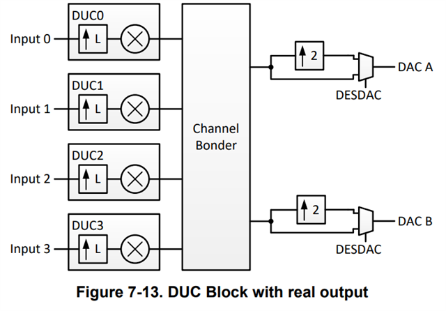
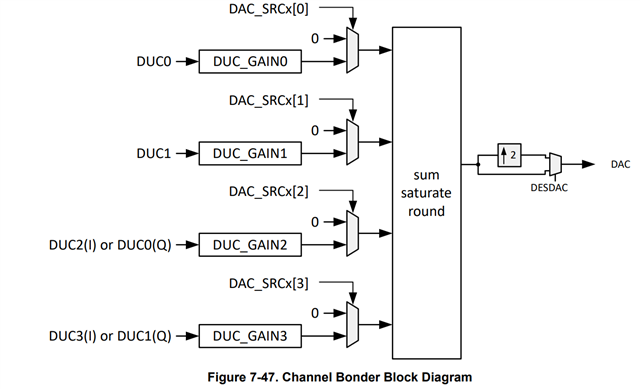
Another question about these converters is regarding the relationship between the digital signals in phase and quadrature, and the analog output signals. In one converter, I noticed that there is the possibility for 4 pairs of digital signals (CH0_I, CH0_Q, CH1_I, CH1_Q, CH2_I, CH2_Q, CH3_I, and CH3_Q) to be transported by the JESD204B/C LANES, however, there are only 2 analog conversion outputs (DACOUTA+, DACOUTA-, DACOUTB+, and DACOUTB-). How does the digital signal relate to the analog signal? For example, do channels CH0_I and CH0_Q control the phase and amplitude of the analog output DACOUTA+.

  • Luiz, 

    Speaking for the DAC39RS12, this device has something called the "channel bonder" on it. This allows any I/Q stream to go to any DAC (for the RF12 there are two DAC channels for the RFS12 there is one). In a JMODE like JMODE3 one could send all four I/Q signals to a single DAC output, allowing one to have multiple modulated signals to be present on the single DAC output. The DUC_GAIN field can digitally attenuate each DUC by -6 or -12dB to allow multiple I/Q streams to go to a signal DAC without digital saturation. In addition, if one only has a single I/Q stream going into the JESD interface they can map it to both DAC outputs (on the DAC39RF12 dual channel device). 


    Regards, 

    Matt

  • Hello Matt,

    I have another question about JESD204B/C communication, specifically about the maximum number of AD/DA converters I can connect to a FPGA. Taking the DAC39RS12 converter as an example, there is a table with various JESD modes. How do I calculate the lane rate, knowing the mode that I will use? Additionally, how can I relate the JESD mode to the maximum frequency I can generate at the analog output (DAC)?

    Best Regards,

    Luiz

  • Hey Luiz, 

    There is a table in the datasheet (Table 7-21) which shows the various JMODES and the different rates. I am in the process of working on a new GUI that will help you with all of these types of things. I am not ready to share it on a public forum but would be happy to email a link to a TI drive copy of the GUI. 

    Let me know if you would like me to email you a link to it. 

    Regards, 

    Matt

  • Hey Matt,

    Yes, I would like to have access to the new GUI. It will help me a lot in the development and prototyping of our solution.

    Thank you so much!

    Regards,

    Luiz.

  • Hi matt

    I am also considering purchasing a DAC39RF10 and am wondering which JESD mode would be best.
    I would like link too if possible.

    I am not sure about the "streams" item in Table 7-21.
    Is it like sending one chunk of data several times?
    I would like to know specifically.

    When outputting 1ch of real waves with JMODE 1, is Lane 8~15 (CH0_Q[7:0]) not used?
    (Cannot be set in the first place?)

    regards,

    masa

  • Masa, 

    A stream is a stream of digital data. In real modoes a single stream is sent to either DACA or DACB. In complex data modes I accounts for one stream and Q the other. In complex data modes each DAC can output up to 4 I/Q data streams at once via. the channel bonder. 

    Your statement about JMODE1 is correct. If the interpolation is set to 1 (real mode) and a single data stream is being used, only 8 lanes will be used by the DAC. the other 8 lanes will not be used. One could also send 2 real data streams via JMODE1 and use all 16 lanes. This would allow  DACA and DACB to have their own streams. 

    Do you know if you plan to use real or complex data and how much data bandwidth you need?

    Regards,

    Matt

  • Hi matt

    I want to output the signal at a sampling frequency of 7.2 GHz and in RF mode.

    I have two ideas.
    The first is to output in real in mode 0.
    The second is to output in mode 2 with a complex interpolation x6.

    The bandwidth is assumed to be 500 MHz.
    Resolution N is not a particular consideration.

    If there is any other good output method, please let me know.

    regards,

    masa

  • Hey Masa, 

    What center frequency range are you targeting? Typically I recommend DES2XL for 1st Nyquist and DES2XH for 2nd Nyquist. With the 0.4*FS bandwidth of the DES2X interpolator You'll be able to generate tones with signal content up to 2.88GHz in 1st Nyquist (DES2XL) and after 4.32Ghz in 2nd Nyquist. In RF mode you may be able to operate in this transition band near the Nyquist boundaries; however you will have the unwanted Nyquist image to content with. 

    Regards, 

    Matt

  • Hi matt

    The center frequency range is 4~6.6 GHz.

    In that case, FCLK can only output at 6.6GHz. That is difficult.
    I am also worried about DES2X because it does not have a frequency response diagram and the data rate is likely to be large.


    regards,

    masa

  • Hi matt

    I have an additional question.

    I do not know how to calculate SYSREF.

    Table 7-3 shows 4 different calculation methods, but I don't know how to use the different formulas.
    I don't understand why SYSREF in the GUI has the value it does.
    Also, in DAC38RF89,
    SYSREF=SPS/N
    N=LCM(CLKJESD_DIV,4xFxK), but sometimes it does not fit.

    regards,

    masa

  • Hey Masa, 

    If the DAC in the system needs deterministic latency, then subclass 1 should be used along with a SYSREF signal. This DAC does not require a SYSREF signal for subclass 0 operation and therefore it can be disregarded if deterministic latency is not needed. 

    Here is an article that goes into subclass 1 operation and touches on the SYSREF frequency calculation. This is for JESD204B, which means 8b10b encoding.

    https://www.ti.com/lit/ml/slap159/slap159.pdf?ts=1717421311748&ref_url=https%253A%252F%252Fwww.google.com%252F

    Matt