This thread has been locked.

If you have a related question, please click the "Ask a related question" button in the top right corner. The newly created question will be automatically linked to this question.

ADS1282EVM-PDK: ADS1282 Input vs Output Data

Part Number: ADS1282EVM-PDK

Hello,

I had a question about the ADS1282 chip as well as the ADCPRO software. My current configuration is: PGA = 1. Ext. Vref = 1.25V, and my input range I'm currently operating under is from 0V to 1.25V. I have been using the following formula to convert the data I am getting from ADCPRO into voltage values: DATA*1/2*Vref / 2^30. And am assuming that whatever values I get from ADCPRO will be in millivolts. I am also using the default digital filter that is preselected on ADCPRO (Sinc + LPF Filter Blocks). I am also using a data rate of 250 SPS and operating this board in unipolar mode. The current problem I am having is that my input data is not quite lining up with what we're getting with out output data. 
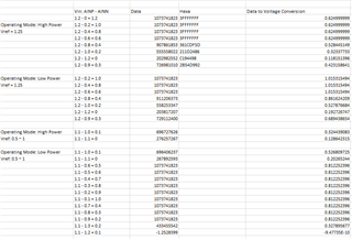
As you can see not even a differential input of zero outputs zero so I am wondering why that is. Another thing, I am using this chip for the project and currently using the ADS1282EVM-PDK board for prototyping. Because we are trying to use our own components with this chip we have decided to take off some components on the eval board. The main components we took out are the Op-Amps as well as the diodes: 
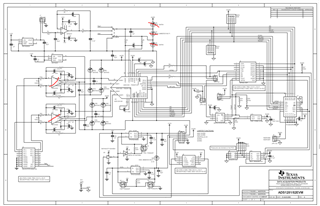
So our external voltage reference as well as our input voltages will go directly into the ADS1282 without having to go through any Op-Amps or diodes that could manipulate the values being inputted. I would also like to know if there is a easy way to convert the output data values from the ADCPRO into the input voltages that were inputted into AINP & AINN. 

Best,

Karam

  • Hi Karam,

    Currently our experts for this device are out of office until next week.  Please be patient for a response.

    Best regards,

    Bob B

  • Hello Karam,

    Since you have bypassed the input amplifier, you will need to level shift your inputs to an acceptable common mode range.

    With the EVM configured for unipolar supply operation (AVSS=GND and AVDD=+5V), the analog inputs AINN and AINP must be in the range of 0.7V to 3.75V.  I suggest setting AINN=VREF=1.25V, and then adjusting AINP from 1.25V to 1.875V, which will result in an input differential voltage of 0V to 0.625V.  Also note that when using VREF=1.25V and PGA=1, your full scale input range will be -0.625V to +0.625V.

    In order to convert the ADCPro data to a voltage, use the following equation:

    Input Voltage = DATA/(2^30-1)*0.5*VREF.  With a full scale input code of DATA=1,073,741,823, your calculated input voltage will be:

    1,073,741,823/1,073,741,823*0.5*1.25V=0.625V.

    Regards,
    Keith Nicholas
    Precision ADC Applications  

  • Hi Keith,

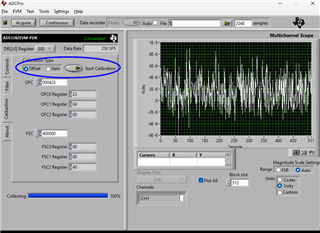
    Thanks for your response. Another question I have is about the calibration mode on ADCPro. I'm trying to figure out a way to have the data monitor output zero whenever the differential between AINP and AINN is zero. I have not been able to do this yet and am wondering if the calibration mode would help. And if it can what should I set the values too, or should I use the automatic calibration button. 

    Best,

    Karam

  • Hello Karam,

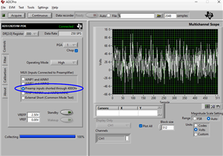
    Yes, you can use the Calibration mode to correct for Offset.  You will need to short the inputs.  You can either short the inputs external to the ADC, or use the internal short.

    After calibration, your offset should be in the range of a few uVs.

    Regards,
    Keith

  • Hello Keith,

    Thank you for your previous response! I now have another question about the ADC1282 Eval Board. So I'm trying to send the raw data from the eval board to a MSP-EXP430FR5969 dev board, through a SPI connection, but I am not entirely sure what pins need to be connected to what on either board. I have seen many diffrent variations of a SPI connection using the MSP-EXP430FR5969 but I am looking for something for my current application with the ADC1282 Eval Board. The reason for this is because when we convert our ADC output data from ADCPro into a temperature value for say room temperature we get signifgantely wrong values. Are there any code references as well as scheamtics that show the best way to interface between these two boards through SPI? Also assuming we configured the two boards correctly, what kind of data can be expect to recieve? Would it still be ADC values some other type of values?

    Thank you for your time!

    Best,

    Karam

  • Hello Karam,

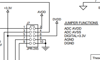
    You will need to disconnect the ADS1282EVM board from the MMB0 board to isolate the digital control signals.  Power can be provided on header J7.  Connect pin 2 to +5V, pin 4 to pin 8 (ground), and pin 6 to +3.3V.

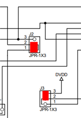
    In order to use the board oscillator, connect a jumper between pins 2-3 on J3 and another jumper between pins 1-2 on J2.

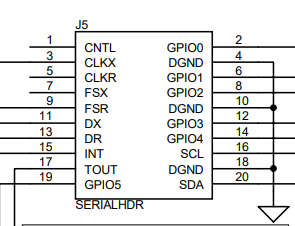
    For SPI interface, you will need to connect SCLK, DOUT, DIN and monitor /DRDY on a GPIO.  These connections are available on header J5.

    SCLK -> J5:3 (CLKX)

    DOUT -> J5:13 (DR)

    DIN -> J5:11 (DX)

    /DRDY -> J5:9 (FSR)

    Regards,
    Keith

  • Hi Keith, 

    Thanks for the quick response! Also, what about the data that we should be expecting from the microcontroller. Should we expect a ADC output, or something else?

    Best,

    Karam

  • Hello Karam,

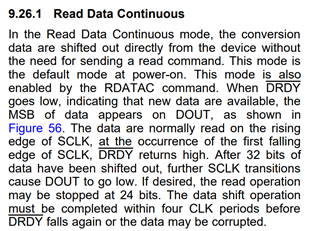
    On power-up reset, the ADS1282 will be in read data continuous mode.  The EVM board uses a 4.096MHz oscillator, so you should see the /DRDY pin toggling at a frequency of 1kHz.

    The microcontroller (MCU) should monitor the /DRDY pin (interrupt) and on the /DRDY falling edge, send either 24 SCLKs or 32 SCLKs to read the conversion result.

    Regards,
    Keith