Part Number: ADS124S08EVM
device ADS124S08EVM
terms of use
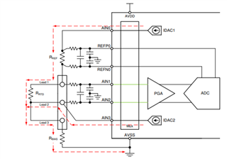
Three-Wire RTD Measurement,
High-Side Reference
ADS124S08IPBS
reading datasheet
Question 1 9.6.1.5 About Digital Filter Selection
With Three-Wire RTD Measurement, there is no need to scan multiple channels in a minimal amount of time.
In this case, I would like to know if a third-order sinc filter (sinc3) is recommended instead of a low-delay filter.
Question 2 9.6.1.6 About Reference Control Register REFP_BUF/REFN_BUF
If 0: Enabled (default), will the reference buffer be disabled?
Also, is it necessary to disable the reference buffer if REFSEL[1:0] is set to 10: Internal 2.5-V reference(1)?
Question 3 9.6.1.6 About Reference Control Register REFSEL[1:0]
For Three-Wire RTD Measurement, High-Side Reference
About Reference input selection
01 : REFP1, REFN1
10: Internal 2.5-V reference
I would like your advice on which one to set.
Question 4 9.6.1.6 About Reference Control Register REFCON[1:0]
Set the operation of the internal reference voltage. It is stated that
Could you please tell me more about setting the operation of the internal reference voltage?
and
If I set it to Internal 2.5-V reference, do I need to set it to one of the following?
01 : Internal reference on, but powers down in power-down mode
10: Internal reference is always on, even in power-down mode
Thank you