Because of the Thanksgiving holiday in the U.S., TI E2E™ design support forum responses may be delayed from November 25 through December 2. Thank you for your patience.

This thread has been locked.

If you have a related question, please click the "Ask a related question" button in the top right corner. The newly created question will be automatically linked to this question.

ADS127L21: Correct usage in bipolar mode

Part Number: ADS127L21
Other Parts Discussed in Thread: INA851, TPS7A39, REF3425, TPS709, REF6025

Hi TI Team

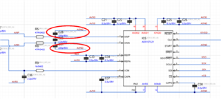
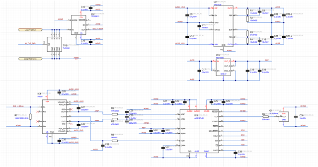
Im planning to use the ADS127L21 in combination with an INA851. I use a +/-5 V supply for the INA851 and a +/-2.5 V supply for the ADC via a TPS7A39 LDO. Since there are no examples of a bipolar supply of the ADS127L21 I'm not so sure about my circuit. Especially about how to supply my REF3425 and if I need to bypass capacitors from AVDD1&2 and AVSS to AGND or if this isn't necessary.

You find the schematic below.
Thank you in advance!

Regards Theo

  • Edit: I also put a Ferrite between AVDD and IOVDD.

  • Hello Theo,

    Overall, this looks good, but I would recommend connecting the input common mode capacitors to AVSS instead of AGND.  This helps provide charge for the common mode AC current flowing through the ADC input pins.

    If you are using the same supply voltage for AVDD and IOVDD, then a ferrite will help reduce digital noise coupling into the ADC inputs.

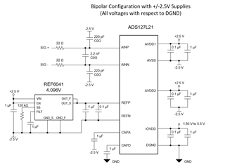
    Below is a recommended configuration for bypass caps and reference circuit when using bipolar supplies.  I think you have duplicated this, except for the input common mode capacitors.

    Regards,
    Keith Nicholas
    Precision ADC Applications

  • Hi Keith

    Thanks for your help! I think I will go for a separate tiny linear regulator for IOVDD instead of using a ferrite. Something like the TPS709 with 1.8V an supply it directly from my +5V to separate it entirely from the analog part.

    Regards Theo

  • Hi Theo,

    Yes, using a separate LDO for IOVDD will likely be a lower noise solution verses sharing IOVDD and AVDD.

    Also, if you want a lower noise reference that can support the highest data rates, the REF6025 will be a better choice.  The REF3425 should work well for low-speed mode, but we have never tested this reference with the ADS127Lxx family of ADCs.

    Regards,
    Keith

  • Hi Keith

    Thanks for this additional info. I will test both references but i will probably use the REF6025.

    I have an additional question regarding the FIR and IIR Filter of the ADS127L21. How much delay do they add to the Signal. 
    If I have a sample frequency of 500SPS I need to calculate the FIR filter with 1000SPS and i use an order of 120. So if I'm correct my delay would be 60ms and I get the "real" new value of the input signal only after this period?
    Since this would be quite long and I need a new value every 20ms i would try the IIR filter instead to just filter between 49-61Hz. How much delay does this filter have with a sampling rate of 500SPS?

    Regards Theo

  • Hello Theo,

    There are additional delays due to the other filter stages in the wideband chain.  As an approximation, you can add 11 more data rate periods.  If you are using 120 taps, then your total latency will be 120/2+11=71 data rate periods.  If your final data rate is 500sps, this will translate to a total latency (full settling time of a step input) of 2ms*71ms=142ms.  Please note that you will get data every 2ms (500sps), but the time needed for 100% settling for a step input will be 142ms.

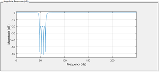
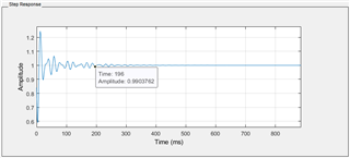
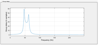
    If you use the IIR filter, the total time is not as straight forward to calculate since the response is 'infinite'.  In this case, you would need to look at the settling time for a step input.  I am not clear on your filter type; are you interested in a passband filter or a notch filter in the 49-61Hz range?  Assuming you want a notch filter, the below response provides -20dB of attenuation between 49Hz and 61Hz.  However, the settling time to 99% of final value is on the order of 200ms.

    However, if you are more interested in frequency domain and signals outside of the notch-band, then the group delay is a better metric.  In the case of the IIR example, input signal frequency less than 15Hz and greater than 90Hz (up to 250Hz Nyquist), the group delay will be less than 1 sample period.

    Regards,
    Keith

  • Hi Keith

    I figured it out by myself using Matlab. It seems that the IIR Filter as a pure low pass is a bit faster then the FIR and its delay seems to be only frequency dependent. So regardless which Sample speed i use the delay at the end seems to be always the same. But since the delay of the FIR is always the same I think I will still use it.

    Thanks again for all your help. Really appreciate it.

    Regards Theo