This thread has been locked.
If you have a related question, please click the "Ask a related question" button in the top right corner. The newly created question will be automatically linked to this question.
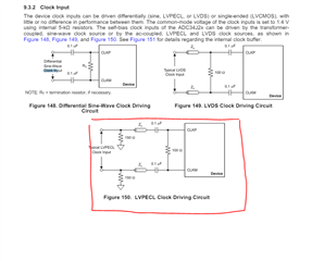
I am looking to drive the ADC34J24 with a CDCLVP1204 as I need to distribute the SYNC to multiple ADC's.
The CDCLVP1204 has LVPECL output but the ADC34J24 requires 0.9V common mode voltage. Not sure how to interface the two devices because the supply to the CDCLVP1204 is 3.3V and the ADC is 1.8V.
Raj,
The CDCLVP1204 output will work, we will just need to move the common mode to the .9V. To do this we can put AC-coupling caps to remove the DC bias on the output of the CDCLVP (.1uF) and then use a voltage divider circuit to bias the outputs to .9V common mode.
Let me know if you have any other questions,
Will
Raj,
Then the CDCLVP will not be the correct part as the LVPECL bias voltage is 2V. I will look into if we have a suitable replacement tomorrow.
Regards,
Will
Raj,
Based on the ADC34J24 datasheet, the clock input must be AC-coupled.
Here is the appropriate termination for the CDCLVP1204 into the ADC.
Regards,
Will
hi Will, I need to distribute the SYNC input and not the CLK input. The CLK input is already AC coupled. The SYNC needs to be DC coupled.
Regards, Raj
Raj,
Sorry for the misunderstanding. I am going to loop in the ADC team to offer a suggestion. I was unable to find the schematic files for the ADC34J24 on ti.com but the ADC team should be able to assist you in understanding what output format your SYNC pulse should be and what the resistor network should look like to interface into their SYNC inputs.
Regards,
Will
Hi Raj,
I would use the LMH5401 or LMH3401 as a level shifter to DC couple from the output of the LMK or CDC device to the ADC sync input pins.
This is how most customers do this interface.
Thanks,
Rob
hi Rob, I ended up using a biased three resistor voltage divider to set the proper terminating voltage and common mode voltage to the ADC34J24.