This thread has been locked.

If you have a related question, please click the "Ask a related question" button in the top right corner. The newly created question will be automatically linked to this question.

ADS8665: Writecommands (and 9-bit address)

Part Number: ADS8665

First time using this part.

I'm using datasheet version SBAS780B – DECEMBER 2016 – REVISED MARCH 2021

There are a couple of things in the Data Sheet that don't seem to match-up (and I can't find an errata sheet).

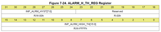
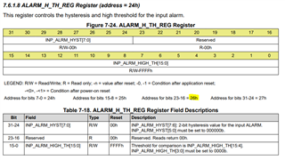
Firstly, on page 41 (Input Command Word and Register Write Operation) for every command it says this:

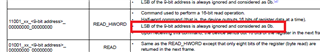
That suggest, if I want to read (or write) register address 0x04 - I left shift the register address by 1 (going from 0b0000 0100 to 0b0000 1000) the ADC will ignore the Least significant bit and read it as 0b0000 0100 (i.e. 0x04).

However in note 1 it says the following:

That suggest the Most Significant Byte is ignored and not the Least Signifciant by (so we don't need to left shift the address).

Which part is correct?

Secondly, on the same page/table, there are three WRITE Commands:

Each register is 32-bits (1 word for this ADC).

All these commands are half-word commands i.e. write 16-bits.

But none of these commands seem to offer a way to select wether you are wirtting to the upper (MS) half-word or the lower (LS) half word.

  • 11010_00_<9-bit address>_<16-bit data>
    • Half-word write command (two bytes of input data are written into the specified address).
      • Does this write to the upper (MS) half-word or the lower (LS) half word?
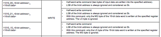
  • 11010_01_<9-bit address>_<16-bit data>
    • With this command, only the MS byte of the 16-bit data word is written at the specified register address. The LS byte is ignored.
      • This suggests the ADC only cares about the lower (LS) 8-bits in <16-bit data>
      • Does this write to the upper (MS) half-word or the lower (LS) half word?
  • 11010_10_<9-bit address>_<16-bit data>
    • With this command, only the LS byte of the 16-bit data word is written at the specified register address. The MS byte is ignored.
      • This suggests the ADC only cares about the upper (MS) 8-bits in <16-bit data>
      • Does this write to the upper (MS) half-word or the lower (LS) half word?

Am I missing something - how do I chose wether I write to the upper (MS) 16-bits or the lower (LS) 16-bits of an ADC Register?

  • Hi Ben,

    Thanks for your question. Let me look into this and get back to you soon.

    Best,
    Samiha

  • Samiha,
    Have you been able to get an answer for this?

  • Hi Ben,

    Thanks for your patience. 

    For the 9-bit address, the MSB will always be 0, per note (1). Additionally, the address can only be even, so the LSB is ignored as it is always 0. So the 9-bit address formatting would be:

    • bit 8 = 0
    • bits [7:0] = even numbered address, where bit 0 is always 0.

    Thanks for your feedback though! We will edit the text to explain this better in the next datasheet revision.

    For the 3 WRITE commands questions:

    Although the entire register is 32 bits, the first 7 bits of the WRITE command are predefined as 11010_xx, the next 9 bits are the address, so the actual data you may write is only 16 bits. 

    • The first WRITE command actually writes all 16 bits of the data.
    • The second WRITE command ignores the LS byte and only writes the MS byte.
    • The third WRITE command ignores the MS byte and only writes the LS byte.

    So assuming you always write all 16 bits of data, you only need to use the first WRITE command, with the first 16 bits of the register as: 1101000<9 bit-address>.

    I hope that helps.

    Best regards,

    Samiha

  • The WRITE commands still doesn't quite makes sense to me.

    Let's say I want to write to the ALARM_H_TH_REG Register at addres 0x24 (0b0010 0100)

    Let's say I want to put 0xFF in INP_ALRM_HYST and 0x00FF in INP_ALRM_HIGH_TH.

    If I can only write 16 bits at a time, I'll have to do two writes.

    • The <9-bit address> will be 0x024 (0b0 0010 0100)
    • The <16-bit data> will be in bith cases 0x00FF (0b 0000 0000 1111 1111)

    So I how do I select which part of the register to write to?

    (I.e. because we can only write 8 or 16-bits at a time - we need a way to select where in the 32-bit register those 8 or 16 bits are written).

    Are there any examples? That may help me under stand this.

  • Hi Ben,

    You would have to write a 16 bit data write command to address 26h to set INP_ALRM_HYST, and the another 16 bit data write command to 24h to set INP_ALRM_HIGH_TH. You cannot write to 25h or 27h, as the address must be even.

    For example, to set 0xFF in INP_ALRM_HYST, you could do:

    1101000 <write> 0 0010 0110 <9 bit address 26h> 1111 1111 0000 0000 <FF00h>

    And repeat with address 24h to set 00FF in INP_ALRM_HIGH_TH.

    Hope that makes sense.

    Best regards,

    Samiha