This thread has been locked.

If you have a related question, please click the "Ask a related question" button in the top right corner. The newly created question will be automatically linked to this question.

ADS124S08: PT1000 design requirements and selection of passive parts

Part Number: ADS124S08

Tool/software:

Hi Team,

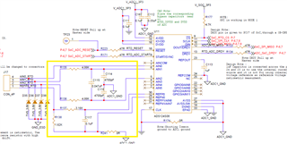
Could you please confirm this, as we are using PT1000 instead of the PT100 used in the reference design do we need to replace the passive parts highlighted in the image below? Can this have any calculations? 

  • Hi Gopika Raj V S,

    Based on the connector, I will assume that this is a 4-wire RTD configuration.  The analog input filter configurations should be fine, but there are a couple of considerations.  If you desire to use any PGA gain beyond a gain of 1 you will need to increase the value of the R138 reference resistor.  There is a trade-off in doing this as you will need to decrease the IDAC current you intend to use so that you do not go beyond the compliance voltage.  The means that the total voltage drop of the current path must be less than the specified compliance voltage as listed in the electrical specifications in the datasheet ((AVDD - AVSS) - 0.6V or (AVDD - AVSS) - 0.4V depending on IDAC current setting).

    More importantly, you have no input protection for the current source coming from AIN0.  Any transient must be limited to +/-10mA maximum through the AIN0 pin.  You could add a series resistor to limit the current, but you will need to make sure the IDAC compliance voltage is being met.  Another option would be to add a series Schottky diode.  However, a diode will only limit current in one direction.

    There are a couple of useful resources.  One is A Basic Guide to RTD Measurements and the other is an RTD calculator tool

    Best regards,

    Bob B