This thread has been locked.

If you have a related question, please click the "Ask a related question" button in the top right corner. The newly created question will be automatically linked to this question.

Test Signal at the TESTP_PACE_OUT1 and TESTN_PACE_OUT2

Other Parts Discussed in Thread: ADS1294, ADS1298

Hi,

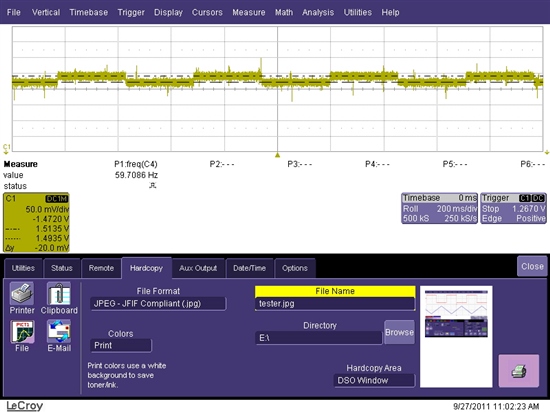
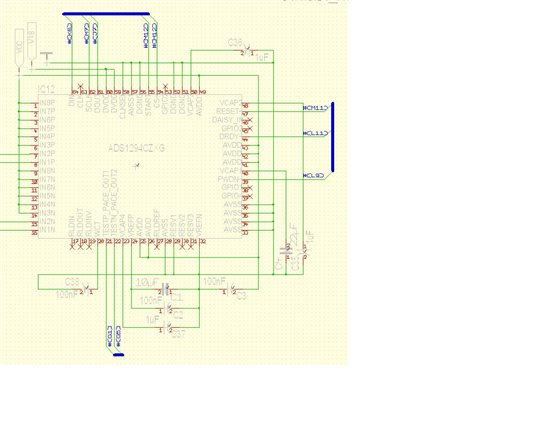
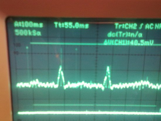
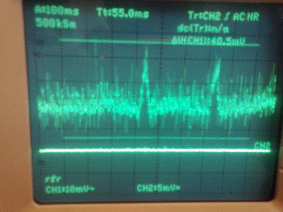
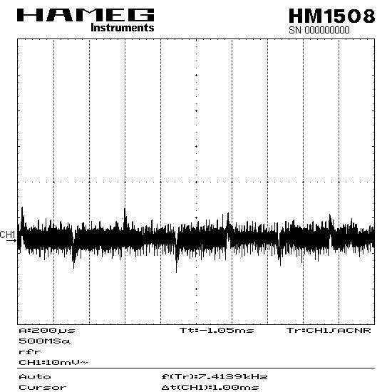
i have a problem to measure the test signal at the TESTP_PACE_OUT1 and TESTN_PACE_OUT2 pins. I have read in the datasheet at page 23 that i can measure the test signal at this pins. I have tested this with the ADS1298ECG-FE where i generate the test signal internally and i see the square-wave-signal in the analysis/scope tool. When i use a oscilloscope and want to see this signal at the TESTP_PACE_OUT1 pin i see only noise and no square-wave-signal. I have all the WCT powered down so that the WCT amplifier isn't connected to the signal path.  

Why can I not measure this signal at this two pins? What am I doing wrong?


Thanks

Eckart

  • Hi Eckart,

    The signal is small. The inverting input of the amplifier is grounded, and the signal is being applied to the non-inverting input. [There is actually an error in the GUI, which says that the test signal amplitude is 2 x Vref / 2.4. It should be 2 x Vref / 2400 (or 2.4mV, rather than 2.4V - on page 47 of ADS129x Datasheet)]. This is called out in the ADC Register tab, Channel Registers > "Test Signal Amplitude". If you convert the test signal, you will see ~50mV p-p (we used a G=12).

    Doing the math: 2.4V x 2 / 2400 = 24mV. If you look at the PACE signal on the scope, and average the noise, you should see a 20mV p-p square wave (as shown in the below scope shot). This is because the PACE amplifier is in a gain of 0.4 => 50mV x 0.4 =20mV (can find this on page 68 of the datasheet).

    Here, the scope probe is connected to TP3 on the MMB0, for GND, and to J5, pins 1 or 2, for the PACE signal (J5 is not installed, but the signal is still available through the bus).

    Regards,

    Michael

  • Hi Michael,

    Thanks for your help. I have tried to get a signal again and it works. I´m getting a square wave signal and the ECG signal at the TestP and TestN pin. It´s really a very small amplitude and changed the settings at my oscilloscope and now it´s fine at the ECG-FE. Now i tried to measure the signal at my own circuit board and i´m getting no signal. No test signal and no ECG. I need it to detect later the pacemaker but when i´m not getting a signal at these pins i can not detect a pacemaker. Otherwise the ADs1294 which i use works correct. I think so. I´m getting a ECG signal and i can see it at my oled display so i think there must be a signal at the TestP or TestN pin. But there´s only noise. I also use the gain of 12. I don´t know if there is a mistake in my Hardware or i forgot a capacitor or resistor e.g. So here is my hardware for the ADS1294:


    I have tried many things and changed the register settings but i´m getting no signal. Have anybody an idea?

    Regards,
    Eckart

  • Hi Eckart,

    My guess would be that it is a register setting. My recommendation is to use the ADS1298ECGFE GUI, set all of the registers accordingly that were successful in using the PACE out lines, and then look at the register table within the GUI to match your configuration with how you are configuring your own device. You may want to read back your register settings to double check they are all set correctly.

    Regards,

    Tony Calabria

  • Hi,

    i have found a problem at the ADS1298ECG-FE. I have measure at the TestN_Pace_Out2 pin and i get a test signal and a ECG Signal. But when i have measure at the TestP_Pace_Out1 pin there´s no test signal and no ECG signal if i connect CH1 and CH2. I changed the register settings several time and i get no signal. So at my own circuit board there´s only connected the TestP_Pace_Out1 pin and not the TestN_Pace_Out2 and that's why i´m getting no signal too. I also have two versions of datasheets where the the Pace detect register settings are different. In the first there controls TestP_Pace_Out1 channel1,3,5,7 and TestN_Pace_Out2 channel2,4,6,8 and the second there controls TestN_Pace_Out2 channel1,3,5,7 and TestP_Pace_Out1 channel2,4,6,8. Which one is the right? Can anybody explain me why there´s only one Test pin working at the ECG-FE? Thank you.


    Best Regards,

    Eckart

  • Hi Eckart,

    PACE_OUT1 is for the even channels and PACE_OUT2 is for the odd channels.

    PACE_OUT1 and PACE_OUT2 can both be accessed at the J5 header. 

    I am not sure what test points you are talking about when you say only one test point is working. Could you elaborate?

    Regards,

    Tony Calabria

  • Hi Tony,

    I have found the problem with a bad connection at the JP36 and the channel 2. Now I see at both pins (Pace_Out1 and Pace_Out2 ) a signal with my oscilloscope. On my own PCB I also see at Pace_Out1 a ECG signal when I now know that for Pace_Out1 I must connect the channel 2. My problem is that when I use the ECG simulator and I have an ECG signal with only a small amplitude of 1mV it´s very difficult  to see a ECG signal at my oscilloscope because of the noise. When I compare the signal of the ECG-FE and of my PCB there´s a big difference of noise. If I change the amplitude to a bigger value like 3mV I can better see the ECG signal but the noise is still high. So if I want  to detect a Pacemaker it would be very difficult. Have you an idea why on my own PCB the noise is so high? I tried to change the register settings like they are on the ECG-FE but nothing happens. I have attached two pictures. The first you see the signal at the Pace_Out1 of your ECG-FE and the second you see the signal at my own PCB

    picture 1 your ECG-FE                                                                                                                                                     

    picture 2 my PCB

    I have used for both a pace maker signal with my ECG simulator. You can see the pace maker spike in the left picture. In the right it´s very difficult to see this spike. Can you help me?

    Regards,

    Eckart


  • Hi Eckart,

    That noise does seem a little high. What are you using for your signal source? Do you have a simulator that you are using or just using a function generator? When I get a chance, I will take a look at our ADS1298ECG-FE board here in the lab and see if I see similar results.

    Regards,

    Tony

  • Hi Eckhart,

    Looks like you are picking up something. Are you using the ADS1298 evaluation board from Texas Instruments or are you using your own board. Using the ADS1298ECG-FE board, I took a quick measurement of the PACE signal to compare to the input signal to get an idea of what type of noise that I see. Keep in mind that the PACE amplifier is in a gain of 0.4V, so if you have a small input signal, it may appear noisier depending on your gain configuration in the device. Below is a picture of my testing using a sine wave and gain of 1. The blue line is the input signal and the red line is the PACE signal.

    I would start by putting a clean sine wave into the system to eliminate any error coming from the signal source. From there, you can begin looking into simulators to see how the signal propagates through the system.

    Regards,

    Tony Calabria

  • Hi Tony,

    I have tested it with a sine wave too and you can look at my result.

    This is my input signal.

    and this is my output signal.

    Regards,

    Eckart

  • Hi Eckart,

    The PACE output amplifier is fixed at a gain of 0.4. This gain is relative to the output of the internal PGA. So, as I can see from your posted pictures, it looks like you have the PGA set to a gain of 1 and are attenuating a noise 5mV sine wave down to about a 2mV amplitude. Try increasing the PGA gain to 6 or 12 and using a cleaner source to repeat the test. You should be able to get a better result.

    Regards,

    Tony Calabria

  • Hi Tony,

    I already have used the gain of 12. So my results are with the highest gain.

    Regards

    Eckart

  • Hi Eckart,

    I have also done the same as Tony, here in the lab. Both he and I are having the same results. Could you please increase the amplitude of the input signal, then take another scope shot of the signals? Another possible issue here is that you may have your inputs set to "Internally shorted". Ensure they are on "Normal Electrode."

    Regards,

    Michael

  • Hi,

    it´s been a long time ago but I have tried and tested different things. But I still have the same problem that there´s to much noise. Now I have measured the SPI DIN line with my oscilloscope and found a not defined signal when the ADS1294 is working. If the ADS1294 is powered down there´s no signal at DIN. I have done two screenshots of this signal with and without working ADS1294

    This is  the picture with working ADS1294. You can see a peak amplitude of about 30mV.

    This is the picture without working ADS1294. You can see normal noise without this high amplitude.

    This noise is at the DIN line and when the ADS1294 is powered down there are no other things using the SPI. So I think this effect must be by the ADS1294. And this signal I can see at the Peace_OUT pin too. I think this signal is added to the normal ECG Signal and this could be the reason for so much noise. Have you an idea where this signal have its seeds in? Or have I take the wrong capacitor for Vcap1... Vcap4 or forgot a capacitor? I´m not to be able to give account of where I get this signal. Can you help me?

    Best Regards,

    Eckart

  • Hi Eckart,

    At this point, it would be guessing, as far as possible culprits. In order to really help you on a better level, we'd need a full schematic. Otherwise, the next question would be: what on your board is running at ~660Hz? & Do you have any 'switches' activating around this frequency (ie. actual switches, or other small capacitors around the input to the device)?

  • Hi Michael,

    I can give you a full schematic but I can´t post it to this forum because of the secrecy of our product we are developing. If you give me your e-mail address I can send the schematic and the PCB to you.

    Regards

    Eckart

  • Hello Eckart,

    After a little review of your schematic, the first major [2] things I see are the following:

    100k Resistors on the input:

    [here's a good reference]

    The thermal resistor noise associated with these are significant (~128.6uV). Whereas, with our EVM setup, we have the 22k resistors (equates to ~4uV).

    Next major thing I see here, is that you need a differential cap between the inputs, as shown below:

    Also, typically, the thermal resistor noise is similar throughout. So, be cautious of using any really large resistor values, for this reason.

  • Hi Michael,

    I regret to say that your hints have not helped. I have change the resistors to 22k and have put the 47 pF cap between the inputs. But the signal is still there. I have made a screenshot again but this time of the Test_Pace_Out Pin of the ADS1294 and not of the SPI DIN Pin. Look at this.

    It´s a frequency of circa 3,3kHz. I have painted some lines to the image because the screenshot tool of my oscilloscope isn't so good. There are missing same important lines. So at my last screenshot I send to you there are missing lines too. I must explain that the frequency of the noise signal at DIN isn't 660Hz but rather 250 Hz (4ms cycle duration) You can see that it´s the same signal but with an other frequency and with pos. and neg. amplitude. The ADS1294 changes the first signal of the DIN pin and generate this signal and put it to the Test_Peace_Out pin.

    Best Regards

    Eckart

  • Eckart,

    Although it is unfortunate that the antialiasing filter didn't do too much good in this case, it's recommended at least for your final design. So, now it seems we should take a closer look at layout. Would you mind sending me the actual Gerber files? The top and bottom assembly layers you sent are not really enough to see what's going on. Also, you mentioned that the frequency components of the noise are ~250Hz. Would you happen to know of anything else on the board that triggers roughly every 4ms? One thing you might also try is to change your converter data rate, to see if the noise components change with data rate.

  • Hi Michael,

    I will send you the Gerber files. I also have changed the frequency of the ADS1294. Normally we use a sample rate of 250Hz but now I have tested with 1kHz and 2kHz. If I use     1kHz the signal of the DIN pin is 1kHz too and when I use 2kHz sample rate the signal of the DIN pin is 2kHz too. But the frequency of the Test_Pace_Out pin is always 3,3KHz whatever the sample rate is used of the ADS. If I have a sample rate of 4kHz or higher of the ADS the frequency of the DIN pin is not higher than 3,3kHz. So I think the problem could be the DRDY interrupt because this is generated at the frequency of the sample rate. But I don´t understand where this signal is generated and why I can see it at the SPI signal line between the microcontroller and the ADS.  

    Regards Eckart

  • Hi Michael,

    I have tried something and perhaps this will help you. I have tested your ECG FE REV A without the MMBO board and used it with an Eval Board of our microcontroller. At this Eval Board there´s only the ADS working on the SPI line nothing else. I have found the same problem that there´s a signal at the SPI DIN line like on my own PCB.

    Regards Eckart

  • Hi Eckart,

    Since the same problem is showing up on multiple lines, then the most likely culprit is that there is noise being coupled through the grounding. This could be due to many things (noisy ground planes in the PCB, EMI from routing the devices on the board, EMI from external sources, or practically anything outside the board of question). But, essentially, it comes down to the same thing, noise coupling (at the approximate frequency listed above) through the ground plane, distorting the signal.

  • Hi Michael,

    but the problem I see is when the ADS1294 is working there are the noise. If the ADS isn't working and I don´t initialize the ADS there´s no noise. I have used for the ADS an own power supply and an own GND and I didn't used the power supply and GND of the PCB. But the noise is still there. So I think the problem I have I´m getting from the ADS.

    Regards

    Eckart