This thread has been locked.

If you have a related question, please click the "Ask a related question" button in the top right corner. The newly created question will be automatically linked to this question.

ADS124S08: IEC 61000-4-6 Conducted immunity test failed in 4 wire PT100 port and IC gets damaged

Part Number: ADS124S08

Tool/software:

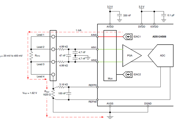
We have designed 4 analog inputs +/-10V and 2 port for four wire PT100. We have placed as per TI guidelines TVS protection diodes in each ports and also place MOVs to earth on each lines, still we are facing issue that IC gets damaged in conducted immunity test while testing 4 wires PT100 port. Is there any way to protect and passed CI test in class A?

Thank you.

Neel Shah

  • We have used TI guideline for PT100 = 4 wires low side reference and as mentioned above also used protection components.

    We got below issue in CI testing.

    Please suggest how could we do through by adding more protection components or through any software algorithm or giving programmable delay for removing aliasing effect?

    Thanks in advance.

  • Hi Neel Shah,

    I know that we have communicated on E2E in the past, but I don't recall seeing the schematic or layout.  Passing the IEC tests can be a challenge. Resolving this could require schematic or PCB layout changes.  One of my colleagues has designed boards specific to thermocouple and RTD inputs and testing the boards through a variety of the IEC tests using the ADS124S08.  We had hoped to post those findings earlier this year but due to shifting priorities this has been delayed.

    Earlier my colleague posted this application note that may be helpful.  Many of the same concepts would apply to pass the IEC tests.  To be of further help I would need to see the schematics and board layout.

    Best regards,

    Bob B

  • Hi Bob,

    We have considered your application note and same things are being applied in our design. We have passed Surge and EFT but face challenge in Conducted immunity test.

    Due to confidentiality, I could not share schematic and layout files.

    Could you please share your thoughts that we may do through by adding more protection components or through any software algorithm or giving programmable delay for removing aliasing effect?

    Please refer below snaps for anti-aliasing filter settings. Could you please guide us on this for 4 channel aliasing effect solution(which is shown in above my chat disturbance between 1.17MHz to 1.6MHz)?

    One last question is that in ADS124S08 IC is having any Butterworth filter design inside the chip which can be coded through software? Is it true?

    I am looking forward to hearing from you.

    Thanks in advance.

    Best regards,

    Neel Shah

  • Hi Neel Shah,

    Unfortunately you are not giving me much to work with.  Think about what you are asking me.  It is essentially 'I have a problem, tell me how to fix it'.  I don't know precisely what you are seeing so it is difficult to determine what action is actually taking place.  I at least need to know what configuration settings you are using, and the raw data you are seeing (which means just ADC output codes without any conversions to temperature, voltage, etc.).  It would also be helpful to know if measurements return to normal after a period of time or if the device requires a reset or power-cycle to correct the issue.

    The programmable conversion delay is primarily used when switching mux channels to prevent charge distribution from one set of channels to the next ones selected.  The mention of the integrated anti-aliasing filter is referring to the filter that reduces the noise of the internal switching frequencies.  It will do very little to any external noise.  See the circled sections below which are the filter components:

    The programmable conversion delay only takes place when switching mux channels when in continuous conversion mode, and when using single-shot mode and starting a conversion.

    The filter sections shown above are the only analog filtering components.  The ADS124S08 is an oversampling device where the analog input is converted to a modulator bit stream.  The modulator data is passed to a digital filter which process the data via a sinc or FIR filter depending on the configuration selected.

    What I think is happening is you are seeing an analog affect prior to the signal entering the ADC input pins.  Any capacitance or inductance will act as a storage element.  If that is the case, then you will need to limit the amount of stored energy.  One method is to use ferrites in series with the input filter resistance to increase the overall filter resistance when high frequency energy is present.  One common mistake is to use too low of resistance or the wrong filtering frequencies.  In some cases customers will only use 100MHz filter peak filtering values.  If you are doing this you may need to add 1000MHz ferrites in addition to your current solution.

    Another consideration is any exposed, unshielded wiring can pick up RFI/EMI.  One area often neglected is if wiring is shielded, it must also be properly terminated and care must be take when connecting the sensor to the PCB.  Small loops of wire at the connection point can defeat the shielding.

    Best regards,

    Bob B

  • Hi Bob, 

    Thanks for the response.

    In our application there is total 6 Ports ADC. 4 of them are used for measuring +/-10V and 2 ports for measuring temperature through 4 wires PT100 sensor which is shown in above block diagram. These data communicated through ADC's SPI to MCU

    These data are reding through our software web tool. Master devise and Analog measurement device communicated through RS485 device.

    As you said, it is possibly to solved through adding ferrite bead in series for the solution of +/-10V measurement. But in PT100 ports we are facing issue that noise are going into ADC and randomly values has been changed and then IC got damaged. It seems through current source channel or through reference REFP0/REFN0 noise is entering in ADC.

    Current source 1mA, ODR = 4K, Fc = 1.046K set through sinc filter.

    Our design is similar to below snaps for PT100. We have just added schottey diodes at current source path and MOVs and TVS placed at input paths to the earth, still noise is injected in ADC. While other +/-10V input ports are not injecting noise in ADC same protection has been at input side (MOVs and TVS). Could you please guide me on this?

    Please note that we are not using EM clamp for testing, we are using CDN device because as per IEC 61000-4-6 suggests CDN for noise injection for the Analog input port testing. We have too little power consumption of device in few mA. Should we use EM clamp for certification?

    if you need any more information then please let me know. 

    Previously I have asked one query that ADS124S08 IC is having any Butterworth filter design inside the chip which can be coded through software? Is it true? 

    I am looking forward to hearing from you.

    Thank you in advance.

    Best Regards, 

    Neel Shah

  • Hi Neel Shah,

    I thought I answered the question regarding the Butterworth filter by showing the diagram of the only analog filtering inside of the device.  There is no Butterworth filter inside of the ADC.  I'm not sure where you got the impression that there was this type of filter.

    As to the issue of damage to the device, the most likely place for this to occur is the IDAC output.  Any transient voltage applied to the pin where the IDAC current is coming out of the device must be limited to no more than +/-10mA.  Using a diode will only help in one direction of current flow.  Using TVS diodes will have a clamp voltage.  If the clamp voltage maximum is greater than the AVDD supply, then you must limit the current to prevent access to the IDAC pin.

    If you are using 1mA current and the reference resistor is 1.6k you may have some additional issues as the compliance voltage is 3.3V - 0.6V or 2.7V for the total voltage drop in the IDAC current path.  It is unclear how high the RTD temperature can go, so let's say it could go to the maximum temperature.  This would mean you could have compliance issues with any added diodes or resistance in the IDAC current path.

    One possible option would be to change the value of the reference resistor to 860 Ohms.  Then instead of the diode use a 1k Ohm series resistance.  The 1k resistance will limit current flow through the ESD structures in both positive and negative excursions.  The compliance voltage will be acceptable for the full range of the RTD resistance.  The downside is you would be limited to a gain of 1.

    Another option would be to lower the current to 500uA while again adding the series resistance.  The difference here is you could raise the series resistance to further limit transient current.

    As to the input type (CDN versus EM clamp), I have no experience regarding one method over the other.

    Best regards,

    Bob B