This thread has been locked.

If you have a related question, please click the "Ask a related question" button in the top right corner. The newly created question will be automatically linked to this question.

DAC53701EVM: No output after setting register values as described

Part Number: DAC53701EVM
Other Parts Discussed in Thread: DAC53701,

Tool/software:

Hello,

I am currently evaluating the DAC53701 device to analyze whether it is suitable for application in our device that is currently designed.

At this moment I use DAC53701EVM hardware and the DAC52701 UI that is available from the TI website.
My final goal is to create medical alarm generation.
My first goal is to create a square wave signal that will control the shutdown pin of my opamp.

The DAC53701 datasheet (SLASEY5) describes on page 48 the steps that should be performed to create a square wave frequency of 610Hz.
Before doing so I performed a reset to have a defined starting position by:
0xD3 (TRIGGER) BIT 9 (DEVICE_CONFIG_RESET) set to 1 in UI. 
After reading out the 0xD3 (TRIGGER) register, BIT 9 (DEVICE_CONFIG_RESET) value is obtained as 0, my assumption is that reset is completed.

Now configuring the DAC to create a square wave of 610Hz according datasheet page 48:

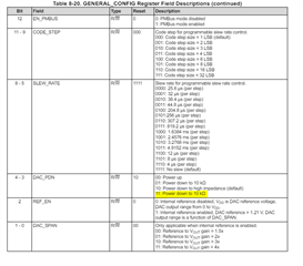
Write GENERAL_CONFIG register (0xD1) to 0xD1 0x58.
Set DAC_MARGIN_HIGH register (0x25) to 0x0F 0xFC.
Set DAC_MARGIN_LOW register (0x26 to 0x00 0x00.
Set TRIGGER register (0xD3) to 0x01 0x00.

Evidence that all register values are set to the required values:


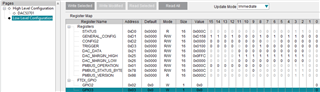
The output of the DAC however does not show any (square wave) signal.
I analyzed the I2C data and all packets contain the expected data and are sent. The DAC acknowledged every byte as normally can be expected.

The settings for the second DAC in a medical alarm set-up are given on page 48 as well, these do also not give any output.

What is missing in the sequence to create a working set-up?

  • Hi Bart,

    You have the power down bits set to '11'. You'll need to set them to '00' to power up the output:

    GENERAL_CONFIG register (0xD1) to 0xD1 0x40. Otherwise your settings look ok.

    Best,

    Katlynne

  • Hello Katlynne,

    Thank you for your reply. With the hint of enabling the output I was able to get a square wave out of the DAC.
    The frequency of the square wave however was 147Hz instead of +/- 600Hz. I managed to change the frequency by following the next specific sequence:
    * Set 0xD1 bits 4 and 3 to 1 (disable output)
    * Set 0xD3 bit 8 to 0 (disable function generation)
    * Change slewrate to desired (see formula 3 of datasheet)
    * Set 0xD3 bit 8 to 1 (enable function generation)
    * Set 0xD1 bits 4 and 3 to 0 (enable output)

    Only when the specific order is followed the output frequency changes.

    Next step in generating the medical alarm is generating the waveform.
    Here again the TI pseudo code does not work.

    This is what I have done so far:
    0xD3 (TRIGGER) BIT 9 (DEVICE_CONFIG_RESET) set to 1 in UI. 
    After reading out the 0xD3 (TRIGGER) register, BIT 9 (DEVICE_CONFIG_RESET) value is obtained as 0, my assumption is that reset is completed.

    Write GENERAL_CONFIG register (0xD1) to 0x1A 0xE8.
    Write CONFIG2 (0xD2) to 0x04 0x00 -> select high prio alarm
    Set DAC_MARGIN_HIGH register (0x25) to 0x0F 0xFC.
    Set DAC_MARGIN_LOW register (0x26 to 0x00 0x00.

    The output does not show the medical alarm waveform as expected.
    Again, all datapackets are correctly sent to the DAC and all are acknowledged.

    Strange phenomena here is that the GENERAL_CONFIG register 0xD1 changes value when read-back after programming the 0x1AE8 value.
    It returns 0x11E8, the CODE_STEP bits (11:9)are set to 000 where are expected to be 101. It seems they are not changed, but for what reason?

    I played with setting the 0xD1 bits 4 and 3 to 0 and setting the 0xD3 bit 8 to 1 but this did not help.


    There might be some dependencies for other register settings as well here but these are not clarified or described in the datasheet.
    Who can help?

  • Hi Bart, 

    Can you try:

    Write GENERAL_CONFIG register (0xD1) to 0x1A 0xE0.

    Read GENERAL_CONFIG register.

    Set DAC_MARGIN_HIGH register (0x25) to 0x0F 0xFC.

    Set DAC_MARGIN_LOW register (0x26 to 0x00 0x00.

    Write CONFIG2 (0xD2) to 0x04 0x00 -> select high prio alarm

    Best,

    Katlynne Jones

  • Hi Katlynne,

    I managed to have the medical alarm function working as well.
    The solution here (again like with the square wave generation) was to first turn-off output, and disable medical alarm function, then make settings to timing etc. and afterwards re-enabling output and medical alarm setting.

    If one tries to update settings like timing with output enabled the values are not actually written/stored in the DAC registers.

    It was a puzzle but we now have a functional demo that can be used for evaluation.

    Thank you for your support in this topic.

  • Hi Bart, 

    Great to hear. I apologize with the confusion in the order of the settings in the datasheet. 

    Please let me know if you end up having any more questions. 

    Best,

    Katlynne Jones