This thread has been locked.

If you have a related question, please click the "Ask a related question" button in the top right corner. The newly created question will be automatically linked to this question.

DAC8775: IOUT Open Circuit detection

Part Number: DAC8775
Other Parts Discussed in Thread: DAC8760,

Tool/software:

Hi TI Team.

When trying to detect open circuit in current mode output, it appears that the ALARMn output is asserted only when the current setting is greater than some 18mA. At currents below 18mA and at any negative current setting, an open circuit is not detected.

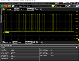
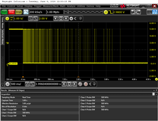
When setting the current at the 'right' setting, it will assert and de-assert the alarm output continuously. Setting the current output just below this point, then at first the ALARMn is not deasserted. Then after a while the ALARMn output starts asserting/de-asserting at smaller and smaller intervals.

Picture #1: Alarm output at 18mA, ALARMn asserts/de-asserts continuously.
Picture #3: Output current setting changed from 12.2mA to 18.1mA. At 12.2mA setting no open circuit is detected, causes the alarm output to finally assert through a lot of assert/de-assert cycles.
Can you elaborate on this, please.

looking forward to hear from you.

BR Henrik Buhl

  • Henrik,


    Offhand, I'm not sure what is causing this problem. However, I do have a few questions and there are things you can check.

    First, does this occur on just one channel or does it appear on all channels. If you're only operating one channel, how are the other channels set up? How is the buck-boost set up for register 0x07? Is the alarm action register 0x0D set to 0x00 for each field? Have you read back the 0x0B status register to make sure the alarm is coming from the channel you're using?

    One of the things that I was thinking was that the load might be too large for the current output. If the slew rate setting was on it would take a longer time to get to a point where the output would lose headroom. You could use the oscilloscope to plot the output voltage with the alarm indication just to check to see how the output behaves. Also, if this is a resistive load, you could use a lower resistance to make sure the voltage doesn't go too high.


    Joseph Wu

  • Hi Joseph,

    A little more info about my setup. I am using a 470 ohm load, and this is happening when I disconnect the load. All 4 channels are setup for current output, but the 3 I am not testing are at 0mA. The DAC8775 is running in full tracking mode.

    I have checked the VPOS/VNEG rails for the channel I am testing on. The open circuit voltage on the VPOS/VNEG rails are the same regardless the current setting. Meaning - it doesn't matter if I get a well defined low ALARMn, an intermittent ALARMn or high ALARMn  - the rails look fine, and at the same level.

    You are mentioning the load being too large (high resistance?) - but this is in open circuit condition. Or maybe I misunderstand you.

    I have not read out the register, I need to check with my sw developer. By the way - I have disconnected the ALARMn output from the MCU to make sure sw doesn't detect and react to the ALARM condition. However, even if sw should react, it doesn't explain why there is no alarm at lower currents.

    I will try to get a read out of the registers.

  • Henrik,


    I misunderstood your question and I think I have a better understanding of the problem.

    In the open-circuit alarm in the device, it should be sensitive enough to show an open circuit even when sourcing ~1uA. Note that there a POC (power-off-condition) bit setting that connects a 30kΩ resistor to the output which might affect this alarm. The POC bit is in the Reset Config Register (0x02) in bit 1. Set this bit to 1 to make sure the open circuit is really an open circuit.

    After that I would use a multimeter to measure the voltage at IOUT. When IOUT is sourcing current (most any value), and there is no load, the output should go up. Once the output goes high enough to hit the positive supply limit of the output amplifier, it should send the alarm. You can use a multimeter to measure the IOUT node and the VPOS_IN_x just to see that the supply starts to track and later is limited.


    Joseph Wu

  • Hi Joseph.

    Our SW guy tested it with his board, and sees the same, but with different level. He gets an open circuit, with a current setting at around 12mA. So it is not completely consistent.

    The POC bit is set to 1, so as I read it the 30k resistor should be disabled (?).

    I measured the IOUT voltage in open circuit conditions. At 20mA setting I get an open circuit voltage on IOUT of 18.6V. With and 1mA setting I get 18.1V.

    At which IOUT voltage level should open circuit be detected?

    BR Henrik

  • Henrik,

    With an open load, I would expect the output to go higher immediately. The buck boost converter would also rise until it hit the upper limit of operation. The output would go all the way up almost to the same voltage as VPOS_IN_x. I've seen this with with single digit DAC codes, where the only output load would be the impedance of the multimeter, and it only takes a couple of microAmps to get the output to the max of approximately VPOS_IN_x.

    Do you have any output protection on the board? I'm asking about any sort of TVS diodes attached to IOUT. I think what might be happening is that as the output rises the TVS diode breaks down and the current through the diode is seen as a load. 

    You can check this by removing any TVS diode on the output and re-running the test. Regardless, I think it might be useful for me to see a copy of the DAC8775 portion of the schematic.

    Joseph Wu

  • Joseph,

    Thank you - 'TVS diode' was the right words. In order to protect the device we had reused the protection scheme from an output configuration with two DAC8760's. This TVS was clamping the IOUT open circuit voltage .

    We need to reconsider this protection.

    BR Henrik Buhl

  • Henrik,

    I'm glad that worked out. I would point out that you still can use a TVS diode, but you just need to use one with a higher voltage. If you look at the DAC8775EVM, the circuit uses a TVS diode on the output as well. It uses a CDSOD323-T36SC (36V) TVS, and you can still see the open circuit detection rather easily. I would note that these diodes do have some leakage that might cause make the open circuit trip after the output is programmed to more than 1uA, but it should still trip with very low current.

    If you have any other questions, you can post back or start a new thread.

    Joseph Wu

  • Thanks again. Due to the configuration of the outputs and the terminals they share, we actually have two TVSs per output. One at the terminal, and one closer to the DAC. This is what tricked me.