- Ask a related questionWhat is a related question?A related question is a question created from another question. When the related question is created, it will be automatically linked to the original question.
Original question:

Tool/software:
Hi!
I'm using the ADS125H01 with an STM32H745.
I have converted the library that is provided to the stm32 and setup SPI.
My SPI setup is:
I am executing
adcStartupRoutine();
startConversions();
After I have setup the SPI and all the peripherals.
My adcStartupRoutine looks like this:
void adcStartupRoutine(void)
{
/* (OPTIONAL) Provide additional delay time for power supply settling */
HAL_Delay(50);
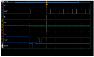
/* (REQUIRED) Set nRESET pin high for ADC operation */
setRESET();
/* (OPTIONAL) Start ADC conversions with HW pin control.
* NOTE: Using the HW pin control here to monitor the nDRDY falling edge.
*/
setSTART(HIGH);
/* (REQUIRED) NO SPI COMMANDS ARE ALLOWED PRIOR TO nDRDY RISING EDGE!
* In case the MCU cannot monitor the nDRDY rising edge during startup,
* for example if the MCU is performing other startup tasks at this time,
* use the nDRDY falling edge as the indicator that the device is ready
* for communication as is done here.
*
* Alternatively, insert a 100 ms delay here if nDRDY pin is not monitored.
* NOTE: Default data rate is 20 SPS => 50 ms conversion period.
*/
pollForDRDY(100);
/* (OPTIONAL) Start ADC conversions with the SPI command.
* This can occur any time after the nDRDY rising edge,
* but is not needed if the START pin has already been set HIGH.
*
* sendCommand(START_OPCODE);
*/
// sendCommand(START_OPCODE);
/* (OPTIONAL) Toggle nRESET pin to assure default register settings. */
/* NOTE: This also ensures that the device registers are unlocked. */
// toggleRESET();
// unlockRegisters();
/* (OPTIONAL) Configure initial device register settings here */
uint8_t initRegisterMap[NUM_REGISTERS];
initRegisterMap[REG_ADDR_ID] = 0x00; /* NOTE: This a read-only register */
initRegisterMap[REG_ADDR_STATUS0] = STATUS0_CLEAR; /* NOTE: This a non-default setting */
initRegisterMap[REG_ADDR_MODE0] = MODE0_DEFAULT;
initRegisterMap[REG_ADDR_MODE1] = MODE1_DEFAULT;
initRegisterMap[REG_ADDR_MODE2] = MODE2_DEFAULT;
initRegisterMap[REG_ADDR_MODE3] = MODE3_DEFAULT;
initRegisterMap[REG_ADDR_REF] = REF_DEFAULT;
initRegisterMap[REG_ADDR_OFCAL0] = OFCAL0_DEFAULT;
initRegisterMap[REG_ADDR_OFCAL1] = OFCAL1_DEFAULT;
initRegisterMap[REG_ADDR_OFCAL2] = OFCAL2_DEFAULT;
initRegisterMap[REG_ADDR_FSCAL0] = FSCAL0_DEFAULT;
initRegisterMap[REG_ADDR_FSCAL1] = FSCAL1_DEFAULT;
initRegisterMap[REG_ADDR_FSCAL2] = FSCAL2_DEFAULT;
initRegisterMap[REG_ADDR_IMUX] = IMUX_DEFAULT;
initRegisterMap[REG_ADDR_IMAG] = IMAG_DEFAULT;
initRegisterMap[REG_ADDR_RESERVED] = RESERVED_DEFAULT;
initRegisterMap[REG_ADDR_MODE4] = MODE4_GAIN_0P25;
initRegisterMap[REG_ADDR_STATUS1] = STATUS1_CLEAR; /* NOTE: This a non-default setting */
initRegisterMap[REG_ADDR_STATUS2] = STATUS2_CLEAR; /* NOTE: This a non-default setting */
/* (OPTIONAL) Write to all registers */
writeMultipleRegisters(REG_ADDR_ID, NUM_REGISTERS, initRegisterMap);
/* (OPTIONAL) Read back all registers */
// readMultipleRegisters(REG_ADDR_ID, NUM_REGISTERS, NULL);
/* (OPTIONAL) Check STATUS register for faults */
// pollForDRDY(100); /* Avoids data not new STATUS flag */
uint8_t status_register = readSingleRegister(REG_ADDR_STATUS0);
printf("Status register %d\r\n", status_register);
}
I have changed the gain to 0.25 as I have an input of up to 10V.
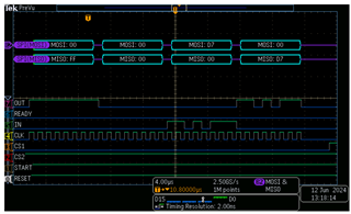
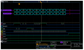
The problem is the following.
I am getting an error when validating the SPI message. The error is that the [2] (3rd element) of the Tx Buffer and the [3] (4th element) of the Rx Buffer do not match when the ADC sends back the result.
Example:
81 - 255
0 - 81
215 - 0
0 - 49
Not 4
SPI Error!
[0] - 81 TXBuffer; For [0] the ADC returns 255, thus 0xff which is good.
[1] - 0 TX; ADC returns [0] of the TX; which is 81 which is good...
[2] same story, everything okay.
[3] here is where it doesn't work, as for every message I send, I get a different CRC value than the ADC returns.
The CRC generating code looks like this (from the library provided by TI)
uint8_t calculateCRC(const uint8_t dataBytes[], uint8_t numBytes)
{
/* Check that "numBytes" is between 1 and 4 */
assert((numBytes >= 1) && (numBytes <= 4));
/* Check that "dataBytes" is not a null pointer */
assert(dataBytes != NULL);
/* NOTE:
* Using "uint_fast8_t" types here instead of "uint8_t" to avoid unnecessary
* implicit type conversions. Reference this E2E thread for additional info:
*/
uint_fast8_t crc = 0xFFu; /* Initial value of crc register */
bool crcMSb; /* Most significant bit of crc byte */
uint_fast8_t poly = 0x07u; /* CRC polynomial byte */
uint_fast8_t shift_by = 0u; /* Intermediate variable */
uint32_t data = 0u; /* Data storage variable */
uint32_t msbMask = 0x80000000u; /* Points to the next data bit */
bool dataMSb; /* Most significant bit of data int */
/* Construct data word from data bytes */
uint_fast8_t i;
for (i = 0; i < numBytes; i++)
{
shift_by = 8 * (numBytes - i - 1);
data |= (((uint32_t) dataBytes[i]) << shift_by);
}
/* Determine the location of the first data byte */
shift_by = 8 * (4 - numBytes);
msbMask >>= shift_by;
/* CRC algorithm */
while (msbMask > 0)
{
// Check MSB's of data and crc
dataMSb = (bool) (data & msbMask);
crcMSb = (bool) (crc & 0x80u);
// Shift crc byte
crc <<= 1;
// Check if XOR operation of MSbs results in additional XOR operation
if (dataMSb ^ crcMSb) { crc ^= poly; }
/* Shift MSb pointer */
msbMask >>= 1;
}
return (uint8_t) (crc & 0xFF);
}
I am also using STM32 function for the SPI transmit and receive:
HAL_SPI_TransmitReceive(&hspi2, DataTx, DataRx, byteLength, 100);
I have also analyzed the protocol with an oscilloscope and the values I have pasted above I am reading on the oscilloscope also.
Is it possible that the library crc check doesn't work properly?
Is my chip maybe damaged?
All the best!