This thread has been locked.

If you have a related question, please click the "Ask a related question" button in the top right corner. The newly created question will be automatically linked to this question.

ADS1298ECGFE-PDK: Unable to read device id of ADS1298 with Arduino

Part Number: ADS1298ECGFE-PDK
Other Parts Discussed in Thread: ADS1298

Tool/software:

Hey there,

I am using ADS1298ECGFE-PKD BOARD. I have unplugged the MMBQ motherboard and working with the ads1298 board. The problem is that when I connect the ads1298 board to an Arduino, I am unable to read the device ID of the board, which stops me from using it. I am receiving 0x00. Do I need to adjust any jumper settings or do I need to make a code change? I've included my Arduino code and connections below; could you please assist me in fixing this?

/*this is arduino coe with ads1298*/
#include <SPI.h>

// Pin definitions
const int CS_PIN = 10;
const int DRDY_PIN = 2;
const int RESET_PIN = 9; // Connect RESET pin of ADS1298 to Arduino pin 9

// ADS1298 Command Definitions
#define RREG 0x20 // Read Register Command
#define RESET 0x06 // Reset Command

// Register Addresses
#define ID_REG 0x00 // ID Register Address

void setup() {
Serial.begin(115200);

// Initialize SPI
SPI.begin();
SPI.setDataMode(SPI_MODE1);
SPI.setClockDivider(SPI_CLOCK_DIV16);
SPI.setBitOrder(MSBFIRST);

// Initialize Chip Select Pin
pinMode(CS_PIN, OUTPUT);
digitalWrite(CS_PIN, HIGH);

// Initialize Data Ready Pin
pinMode(DRDY_PIN, INPUT);

// Initialize Reset Pin
pinMode(RESET_PIN, OUTPUT);
digitalWrite(RESET_PIN, HIGH);

// Power up sequence
powerUpADS1298();

// Reset the ADS1298
resetADS1298();
delay(100); // Give some time for reset to complete
}

void loop() {
// Read Device ID
byte deviceID = readRegister(ID_REG);
Serial.print("Device ID: 0x");
Serial.println(deviceID, HEX);

// Delay between reads
delay(1000); // Adjust the delay as needed (e.g., 1 second)
}

void powerUpADS1298() {
// Power up sequence: Ensure AVDD is up before DVDD
// Assume AVDD and DVDD are connected to appropriate power supplies
// This function is just a placeholder if you need to handle any specific power-up logic
delay(100); // Ensure proper delay after power-up
}

void resetADS1298() {
// Hardware reset
digitalWrite(RESET_PIN, LOW);
delay(10); // Hold reset low for 10ms
digitalWrite(RESET_PIN, HIGH);
delay(10); // Delay after reset

// Software reset (optional, depending on your setup)
digitalWrite(CS_PIN, LOW);
SPI.transfer(RESET);
digitalWrite(CS_PIN, HIGH);
delay(10); // Delay after software reset
}

byte readRegister(byte address) {
byte result = 0;

digitalWrite(CS_PIN, LOW);
delay(1); // Small delay after pulling CS low

// Send the RREG command along with the address
SPI.transfer(RREG | address);
delayMicroseconds(10); // Small delay for command processing

// Send the number of registers to read minus one (0 means 1 register)
SPI.transfer(0x00);
delayMicroseconds(10); // Small delay for command processing

// Read the result
result = SPI.transfer(0x00);

digitalWrite(CS_PIN, HIGH);
delay(1); // Small delay after pulling CS high

return result;
}

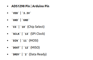
/*this is pin configurations with Arduino*/

  • Hello Ajay,

    Thank you for your post. Have you first sent the SDATAC command before attempting to read registers? 

    Please also see our FAQ page on the ADS129x device family in case some of the topics are of interest to you as well.

    Link to BIOFAQ homepage

    Regards,

    Ryan

  • Hello Ryan
    Thank you for your response. Although I sent the SDATAC instruction before reading the data, the device ID is still not being read; instead, we are seeing the output 0x00 or 0xFF.
    Could you please let us know which jumper settings to set up in order to use it with Arduino? Another issue also emerged: as you can see in the image below, we are unable to obtain the device ID when we connect the ads1298 board to the MMBQ mother board and attempt to read data using software. we become stuck in read registers.


    The data rate change automatically 500SPS to 4000SPS and it got stuck there. After completion of it we get this type of error.

    can you please help us to solve this problem?

  • Hi Ajay,

    For interfacing the EVM daughterboard with Arduino, you will have to consult the schematics in the EVM User Guide and determine the necessary jumper settings and flywire connections required. The documentation for SPI timing, register map, and command definitions is all contained in the ADS1298 device data sheet.

    Does the above error message occur when connecting the MMB0 + ADS1298EVM in their default jumper settings? Can  you share a screenshot of the Device Manager window to show how the EVM is enumerating?

    Regards,

    Ryan

  • Yes, that problem happens when we connect MMB0 to ADS1298EVM using the default jumper configuration. As seen in the image below, we are able to identify devices in device manager.

  • Hi Ajay,

    The EVM seems to be enumerating correctly. I would try the following:

    1. Power-down the MMB0+EVM by disconnecting the external 6V supply
    2. Disconnect USB from PC
    3. Close GUI
    4. Power-up EVM+MMB0
    5. Connect USB to PC
    6. Press and hold RESET on MMB0 (S3), then release.
    7. Start GUI

    The 7-segment display on the MMB0 should show a lowercase "b" after start-up. The GUI should be able to download the firmware automatically and display the Device ID and FW version as shown below:

    Regards,

    Ryan

  • As per your suggestion, I followed the above step and it worked. However, after that, I disconnected the mmb0 board and connected Arduino to ads1298 once more. Then after completing my work i connected back, it to mmb0 board but this time, the problem reappeared and it could not be resolved using this method; as you can see in the image below, the seven segments on the board is giving 'e'.

    Now please suggest me what to do next?

  • Hello Ajay,

    I'm glad to hear that the suggestions did work, at least momentarily. All I can think of is to try a different USB port or restart the PC. For future use, I would always shut down the software, and disconnect USB and power when switching over to Arduino.

    By chance do you have the MMB0 connected through a USB hub? If so, it may be better to connect directly to the PC's USB port.

    Regards,

    Ryan

  • That issue has been resolved. The board was not working at 3.3V, so I set the JP24 to 1-2, which is 1.8V. The board operates at 1.8V I believe that at 3.3V, the I/O becomes damaged and stops functioning. But thank you so much Ryan for your advice.

  • Hello Ajay, 

    Thanks for the feedback! I'm glad you have a working solution now. - Ryan