ADS1014-Q1: Resolution

Part Number: ADS1014-Q1
Other Parts Discussed in Thread: ADS1114-Q1,

Tool/software:

Hi team,

My customer want to know resolution. Here is their settings: VDD=5V, INP=2.5V+/-1.5V, INN=GND, FSR=+/-2.048V(default)

In their use case, I think they can't read 2.048~4.0V information due to over range. Is my understanding correct?

If they want to read 0~4.096V, they should change INN=2.5V, right?

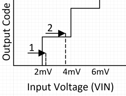
And also I want to know 1LSB threshold. When digital data will increment? (e.g. LSB=2mV setting, not incremented when change 2mV to 3.9mV)

Regards,

Youhei MIYAOKA

  • Hello Youhei-san, 

    The first way you will be able to read the full range is keeping INN=GND and changing the FSR=+/-4.096V in the configuration. This method allows the input signal to fit within the INP range of 1-4V.

    The preferred method would be as you've said, is changing INN=2.5V, with the differential input of +/-1.5V falling between the range of the FSR=+/-2.048V. 

    I will get back to you with a visual related to your question about the 1LSB tomorrow. 

    Would you be able to include customer name and project info into the notes field of the Thread Tracking Toolkit?

    Best, 

    Andrew

  • Hi Andrew,

    Thanks. I updated information on note filed. 

    Actually this is already RTMed project, it is difficult for hardware change. 

    So I think register setting change is one of option. Is there any option? I think ADS1114-Q1 have higher resolution and pin-compatible.

    If they want to keep resolution, this can be option. Is this correct?

    Regards,

    Youhei

  • Hello Youhei-san,


    Without being able to change the hardware, changing the configuration register to FSR=±4.096V will be the best option for the input range. This would mean the LSB=2mV. 

    The ADS1114-Q1 is pin compatible, offering a 16bit resolution.

    Using the ADS1114-Q1 the Maximum Sample Rate will decrease from 3300 SPS of the ADS1014-Q1 to 860 SPS of the ADS1114-Q1 which might affect the customers system.  

    Using the ADS1114-Q1 at FSR=±4.096 the LSB=125uV, offering a higher precision than the 12bit ADS1014-Q1 and would capture the desired range of INP=2.5±1.5V.


    Best,

    Andrew

  • Hello Youhei-san, 

    The image below shows the two scenarios with LSB=2mV:

    Arrow 1 shows that increasing VIN smaller than 1LSB can cause the digital data to increment.

    Arrow 2 shows that increasing VIN the same amount as Arrow 1 in a different location of the code transition will not cause the digital data to increment. 

    It is important to note that the "Ideal Code Output" excludes effects of noise, INL, offset, and gain error which can affect the location of the digital increment. 

    Best, 

    Andrew

  • Hi Andrew,

    Appreciate for your support.

    Regards,

    Youhei