Tool/software:
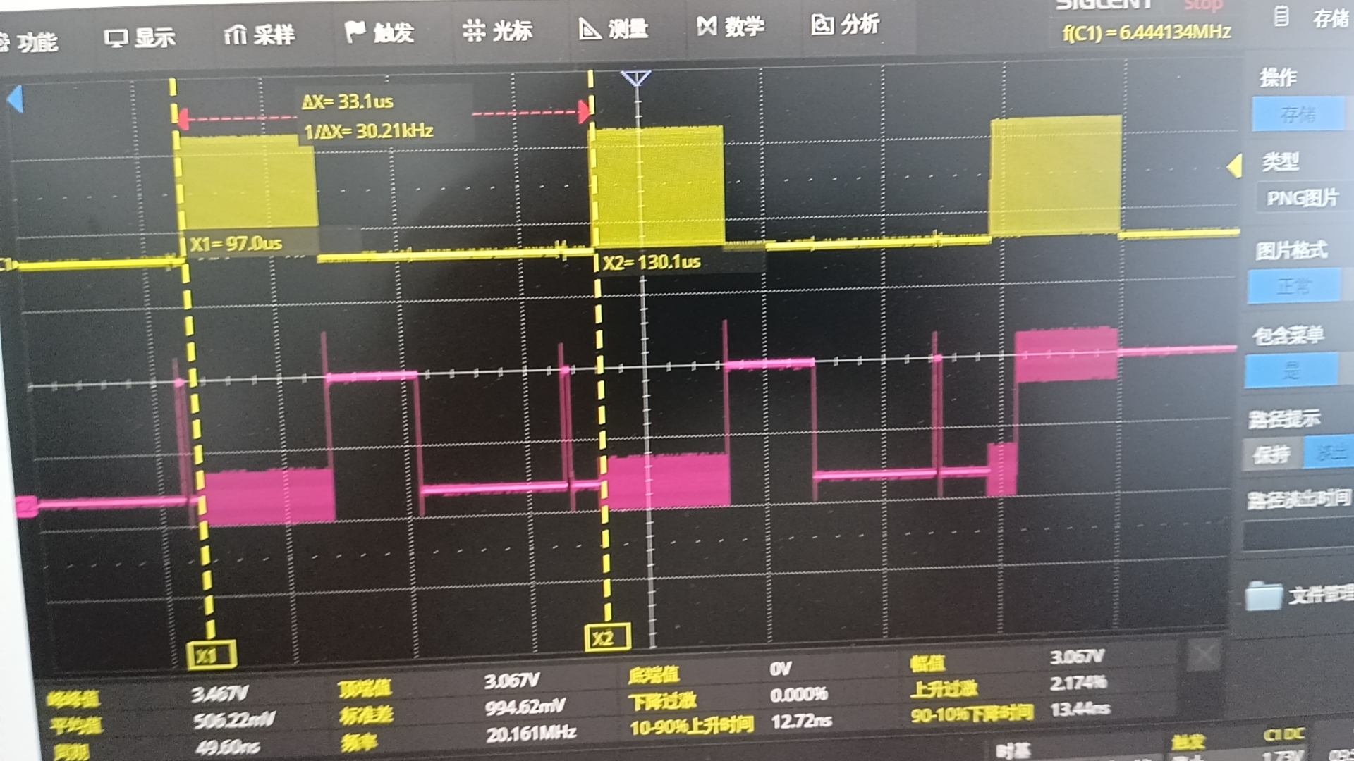
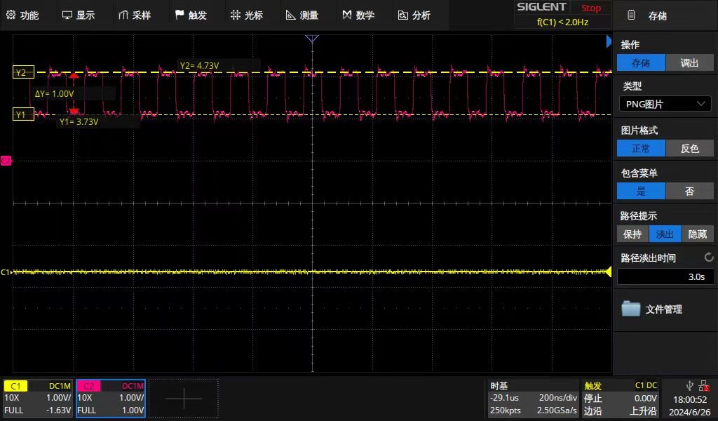
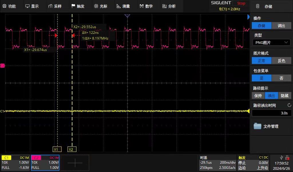
I had some problems reading the ADS131m08, my engineering design and configuration was this: I used the STM32H743 as the master. The SPI clock is set to 20M and the ADS131mM08 clock is set to 8.192M. The sample rate is set to 32KSPS. Set to SPI+DMA mode to communicate with ADS131M08, the DRDY line of ADS131M08 triggers interrupt to inform STM32H743 to read data, enables DMA transmission in the interrupt function of STM32H743, and enables DMA interrupt. Each time 27 bytes of data are read (each word length is 24bits, a total of 8 words), and each time when DMA transmission data is enabled, it determines whether the last DMA has been transmitted. A flag is set to false when DMA is enabled to transfer data, and then the flag is set to true in the DMA interrupt function, indicating that the current data is read. Now my problem is that DMA transfers data out of order with DRDY external interrupts probabilistic sending disorder. This means that sometimes the data transfer is synchronized with the DRDY interrupt, as shown in Figure 1 below. Where the red line is DRDY and the yellow line is SPI CLK, it can be seen that the period of DRDY is 32k. I recorded The Times of DRDY interrupt and DMA interrupt completion in the program, and found that the two counts are about 32K in 1 second, and the two counts are equal. Sometimes there are problems with data transmission, as shown in Figure 2 below. DRDY is the red line, so why is there a pulse bump in the middle of a drdy cycle? And this pulse may cause a STM32H43 external interrupt, because the two counts mentioned above are no longer equal, the number of drdy interrupts in 1 second is about 40K, while the DMA transfer completion interrupt is about 31K. What is the cause of this problem and how to solve or avoid it? thank you.
Figure 1: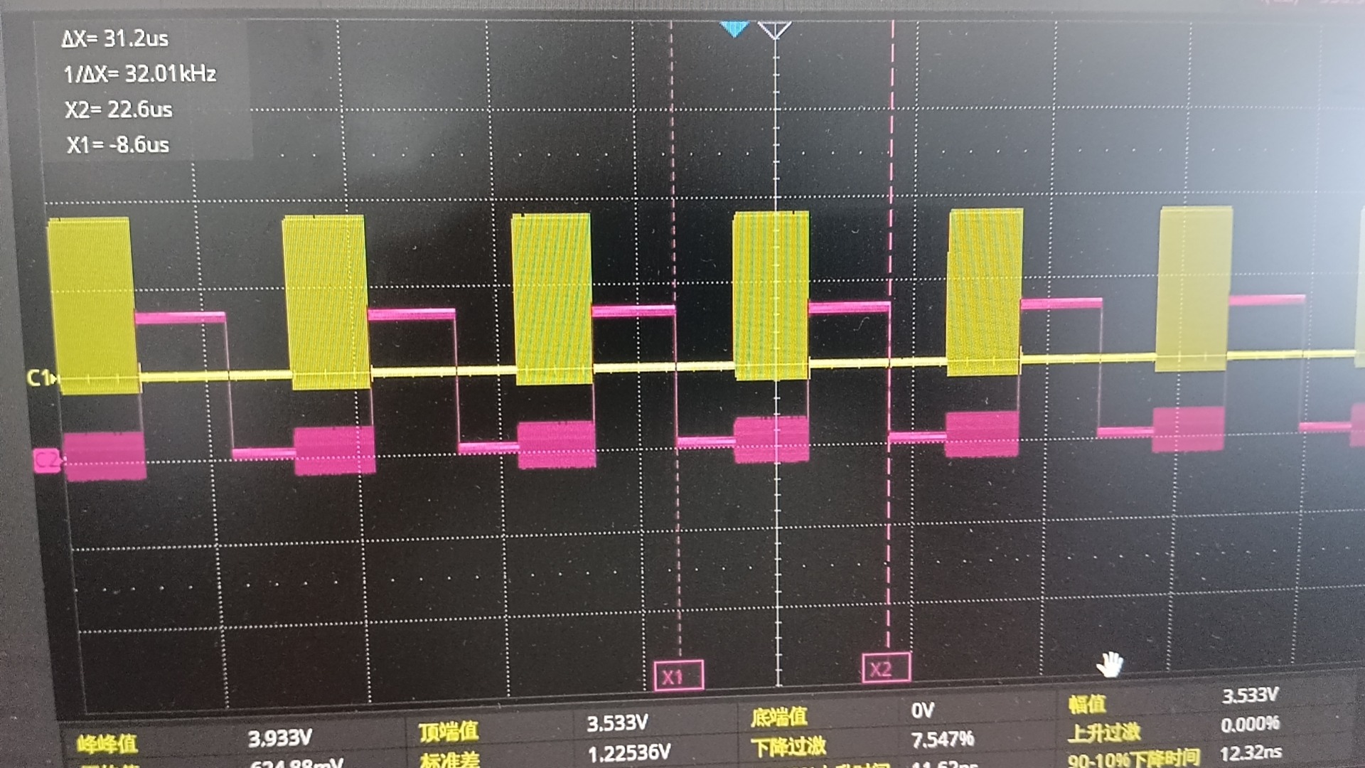
Figure 2: