This thread has been locked.

If you have a related question, please click the "Ask a related question" button in the top right corner. The newly created question will be automatically linked to this question.

LMP92066: UCOR=1 and COR=1

Part Number: LMP92066

Tool/software:

Hello Support team,

My customer observed UCOR=1 and COR=1 when reading 0x0F.
Could you please advise what causes this issue?

The following items are what I requested and got from the customer to help solve this issue.
=====
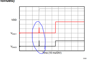
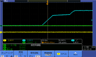
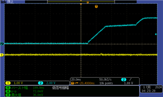
- The transient behavior at DACx outputs at power up as indicated in 9.4.2 At Power Up and Figure 50 in the datasheet is not observed.
- Reading 0x0F register is 0x06 (UCOR=1 and COR=1) right after power on. Then change the access level to Level 2, and write C32 to register 0x10 (software reset), the reading of 0x0F is 0x06. Because the Access level returned to Level 0, software reset seems to be effective.
- Communication between LMP92066 and the host is normal. The slave address set on LMP92066 and the setting at the host is the same. Other registers work normally. DAC output voltage can be changed arbitrarily.
- The circuit board is designed by the customer.
- The LMP92066 the customer is evaluating was purchased from some EC site such as Digi-Key.
=====

Could you please advise what issue could happen and what measures could be taken? Or is the LMP92066 the customer is evaluating abnormal?

Best Regards,
Katsuhiro

  • Hi Katsuhiro,

    Is this a fresh device? Has the customer tried programming custom code into the EEPROM? The errors you see indicate there are EEPROM issues, though this could also be because it's a new device. If the device otherwise responds to your commands, that's a good sign.

    Could you tell me more about the power up behavior? Are you operating in the negative or positive range? The first section of the graph is the transient data you should see. The second section of the graph is dependent on what you programmed into the LUT. If there is nothing programmed, the DACs will stay at zero scale.

    Thanks,
    Erin

  • Hi Erin,

    I will confirm with the customer if this is a fresh device.
    I will confirm if the customer tried programming custom code into the EEPROM.
    Do you mean if it's a new device and EEPROM has not been programmed, UCOR=1 and COR=1 could happen?

    Does your question "Are you operating in the negative or positive range?" mean VDACx output range is positive (VDDB=5V, VSSB=GNDA) or negative (VDDB=GNDA, VSSB=-5V)?
    I had asked the customer to confirm the transient of the first section in the graph at which the DACx outputs follow the VDD until the VDD reaches 4.1V. The purpose is to verify if the power-on-reset operates normally. The customer answered that they didn't observe the transient behavior at the VDACx output voltage.

    Best Regards,
    Miyamoto

  • Hi Miyamoto-san,

    If it is a new device, the EEPROM may act strange until you program it once. If the device was previously programmed and you see the errors, try reprogramming the EEPROM, it could indicate there is corruption. 

    Yes, I was asking about the VDAC output range because I thought the power-on transient might be different between the positive and negative range, but after reviewing the device more it looks like it should operate the same.

    Could your customers potentially capture an oscilloscope screenshot of the power-on sequence and share it with us?

    Thanks,
    Erin

  • Hi Erin,

    Thank you for your quick feedback.
    I asked the customer to examine the EEPROM program and to share the oscilloscope screenshot of the power-on sequence, and I am waiting for their feedback.

    Best Regards,
    Katsuhiro

  • Hi Erin,

    The customer confirmed that by writing to the EEPROM (writing E4 to 0x0F), the reading of 0x0F changes to 0x00.

    Attached are screenshots of the oscilloscope plot of the VDAC output in response to power-on. Even after writing to the EEPROM and clearing the errors, no transient waveform of the VDAC output synchronized with the power-on was observed.

    Before writing to the EEPROM:
    - Light blue: VDD
    - Yellow: DAC 1 (DAC0 shows the same waveform)
    - Green: Irrelevant waveform. Please ignore it.

    After writing to the EEPROM:
    - Light blue: VDD
    - Yellow: DAC 1 (DAC0 shows the same waveform)

    The error has been cleared, but do you know why no transient waveform of the VDAC output synchronized with the power-on was observed?

    Best Regards,
    Katsuhiro

  • Hi Katsuhiro,

    My assumption would be that since your VDD ramp rate is significantly slower (milliseconds as opposed to microseconds), the output does not follow VDD as closely. You can see a small blip on the second graph. But mainly, if your device operates after startup as expected, you do not need to worry about the lack of VDAC power on spike.

    Thanks,
    Erin

  • Hi Erin,

    I see. That would be reasonable. Thank you for your kind support.

    Best Regards,
    Katsuhiro