This thread has been locked.

If you have a related question, please click the "Ask a related question" button in the top right corner. The newly created question will be automatically linked to this question.

DAC8740H: Does the power-up and power-down sequences for AVDD and IOVDD matter?

Part Number: DAC8740H

Tool/software:

We have recently started to use the TI DAC8740H HART modem in our product. While performing some basic product testing we noticed that HART communication is not always working. After more detailed investigation we have observed that the DAC8740H HART modem is dead after power cycle.


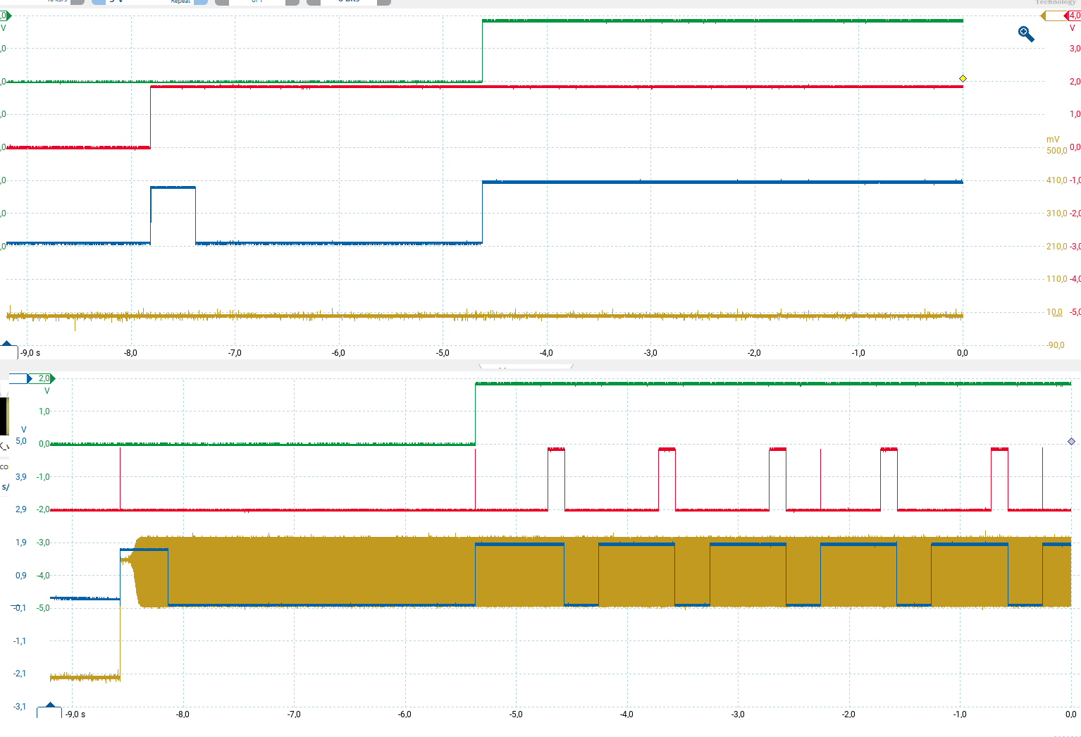
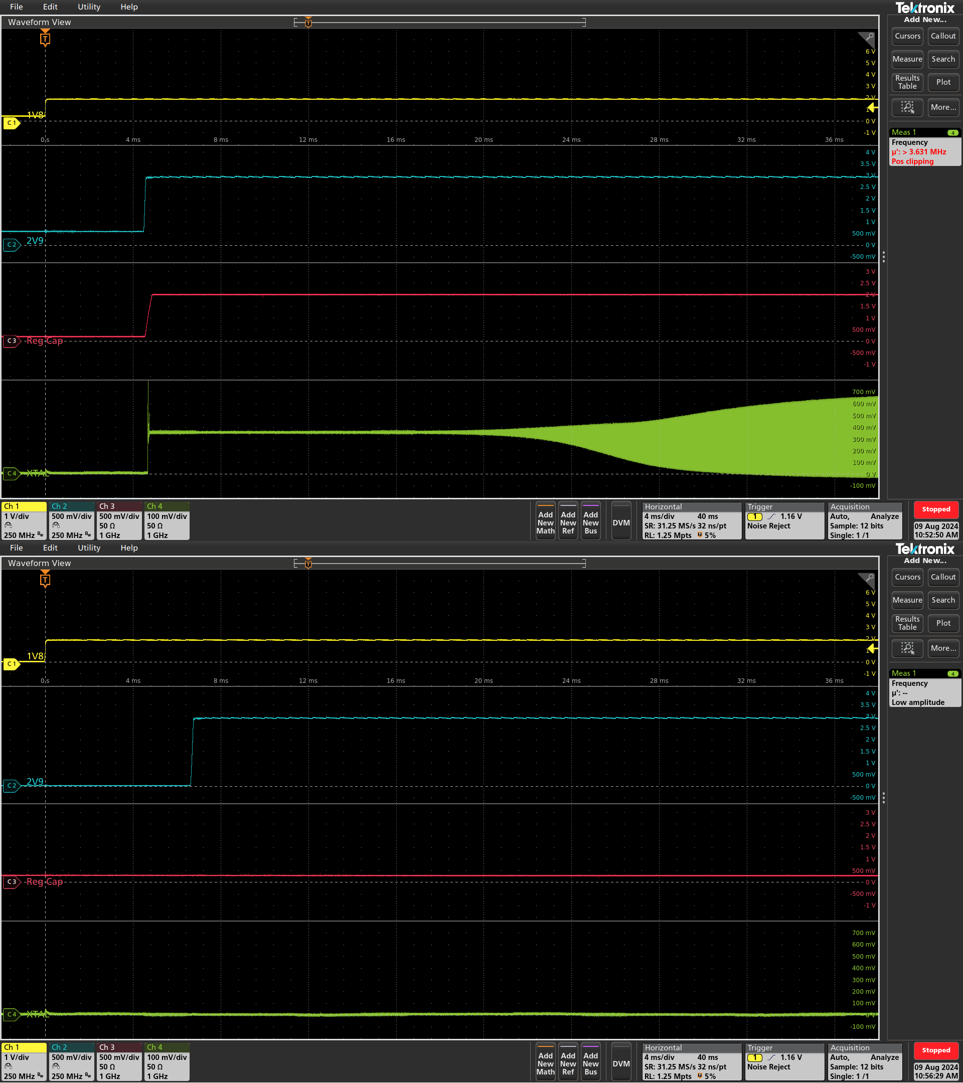
We have external oscillator attached to the DAC8740H and AVDD supply is 2.9 V and IOVDD supply is 1.8 V. In the dead situation the external crystal oscillator is not started and the REG_CAP pin show low voltage. In our design we provide first IOVDD and approximately after 6 ms AVDD is put on. If we reverse the supply voltage order then we are not able to see the dead situation.


From the datasheet I could not find if the order for the AVDD and IOVDD matters? What do you experts think about this problem?

  • Peter,

    I don't know of any dependence of the device operation (or oscillator) on the order of the supply power. As far as I know, we haven't received that as feedback from anyone. Generally we do look at this when we characterize the device and we would report any similar issues in the Power Supply Recommendations (Section 10 in the datasheet - page 37). In this device, there wasn't anything noted in the datasheet, and characterization didn't see it either.

    If it is the crystal having problems with startup, what crystal are you using? Often there is some stray capacitance on the board, which would alter what you would normally need as part of the load. I would try reducing the capacitor values, starting 10pF capacitances, and run the startup test again. It doesn't seem like the startup of AVDD and IOVDD would normally affect this, but it is certainly worth the try.

    Joseph Wu

  • Joseph,

    Please look at the picture below. Does the first part look like the crystal is having a problem to start?

    GREEN      -> RESET
    RED           -> CD
    BLUE         -> RTS
    YELLOW   -> X1

  • Hi Peter, 

    Thanks for the figures. Joe will review and provide a comment today. 

    Best,

    Katlynne Jones

  • Peter,


    It does look like the second device is not starting up. The oscillator is constructed like a Pierce oscillator, with a logical inverter at around the crystal, with capacitive loads on either sides of the crystal.

    In the diagrams, the bottom plot of yellow is X1, and the output should be oscillating between some lower to some higher voltage. In the top diagram, it looks like the X1 voltage is stuck low. For that to happen, I would have guessed that there would be no supply at the device.

    Again, I'm not sure what could cause that. I would have guessed that the supply wasn't connected. X1 at low, and I would guess that X2 is high. For the HART to operate, the device needs the oscillator to run, or none of the HART timing would work.


    Joseph Wu

  • Hello Joseph,

    The previous picture top and bottom are from the same device. Here is another picture from that same device. Top part is where everything is working again normally and bottom is where the chip is not functioning. Check how the supply voltage is applied. In fault situation the Reg cap voltage is not starting to rise. If in the dead situation the 2V9 is removed and re-applied then the chip starts to work again. What is triggering or preventing Reg Cap from rising? What else can we do to debug this issue?

    Peter

  • Peter,


    Again, I don't have a good answer for you on this. I haven't found a previous case where the internal LDO didn't start up. However, if it is the LDO, maybe there's a way to coax it on at the device powers up.

    If the LDO is too loaded at startup, maybe you can try to reduce the REG_CAP capacitance by an order of magnitude from 1uF to 0.1uF. This would see if the initial current to fill the cap is loading down the LDO before it starts. Another possible test would be to keep the REG_CAP capacitance, and raise the AVDD capacitance to 1uF from 0.1uF. In that case you start the power-up slower, and as the internal LDO starts, there's more charge to draw from.


    Joseph Wu

  • Hello Joseph,

    We did the following tests:

    - If we put 100 kohm resistor next to the REG_CAP (1 uF) capacitor we are not able to reproduce the problem.
    - In the dead situation if we supply the REC_CAP with external power supply (1V7) then the chip start to work. As soon as the external voltage is removed the chip return to the dead situation.
    - We changed the REG_CAP capacitance from 1 uF to 0,47 uF and we are not able to reproduce the problem.

    Will this help you to understand what is going on?

    Peter

  • Hi Peter, 

    Thanks for the additional information. Joseph will take a look and provide a response soon. 

    Best,

    Katlynne Jones

  • Peter, 

    At this point, my best guess is that the initial load from the CAP combined with another internal load from a lack of AVDD from the is causing a start up problem. I would expect the latter two results (where suppling an external 1.7V supply to REG_CAP, and lowering the capacitance of the load) to help the start up, which is why you don't see the issue. I would not have expected a parallel 100kΩ resistor to help.

    It does seem that lowering the REG_CAP does help. I would also expect that adding a tiny series resistance with the load cap would also help. You can try adding a 1Ω series resistance or using a tantalum capacitance may remove this problem. For many ceramic capacitors, the ESR (equivalent series resistance) may be exceedingly small. The internal LDO in the DAC8740H may have a problem starting up without the AVDD. 

    Joseph Wu