This thread has been locked.

If you have a related question, please click the "Ask a related question" button in the top right corner. The newly created question will be automatically linked to this question.

ADS124S08: No Exitation current

Part Number: ADS124S08

Tool/software:

Hello, 

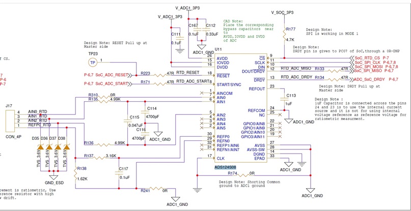
Designed a circuit to Measure Temperature using RTD.The SPI interfaces are working fine, but the Exitation current is Zero, though its SET to 1uA.Schematics attached. 

The Analog voltage and Digital voltage is 3.3.V,

Exitation current is 1mA,

PT 1000 RTD is used..
The AIN0 is configure as a current source pin.

Is there there anything else to consider to enable the current flow. ? is the head room of 0.7v oke in the current source path ?

Thanks,

Sobin

  • Hi Sobin,

    Your image is too small to read, please upload it again. Did you enable the internal voltage reference through the REFREFCON[1:0] bits in the Reference Control Register? it must be turned on and powered on to use the IDACs even though you are using the ratiometric measurement.

    BR,

    Dale

  • Thank for the suggestion, I have uploaded the schematics.

    Is it okay to okay to enable REFP1 and REFN1, since REFP0 and REFN0 is configured to measure voltage across rsense for RTD.?

  • Hi Dale, 

    Now the issue arrised by Sobin is resolved. Now we are able to write but unable to read from the converter. Could you please help in this? 

  • Hi Dale,

    Adding to the previous query, we are trying to read the converted value by making the START/SYNC and DRDY to low. But we are always getting a negative value of 255. Could you please confirm are we missing any basic configuration in reading? Could you please explain in detail how read is done using the command?

  • Hi Gopika,

    You question: Is it okay to enable REFP1 and REFN1, since REFP0 and REFN0 is configured to measure voltage across rsense for RTD.?

    DL: You can not enable REFP1/REFN1 because you are using REFP0/REFN0 for ratiometric measurement, you have to set REFSEL[1:0] to 00 to select REFP0/REFN0. You can enable the positive reference buffer via the bit 5 in the REF register, but disable the negative reference buffer via the bit 4 in the REF register.

    You question:  Adding to the previous query, we are trying to read the converted value by making the START/SYNC and DRDY to low. But we are always getting a negative value of 255. Could you please confirm are we missing any basic configuration in reading? Could you please explain in detail how read is done using the command?

    DL: Are you using START command to start a conversion? Are you using Single-shot Conversion mode or Continuous Conversion Mode? The ADS124S08 datasheet has stated the details to read the conversion data, please see the section 9.4.4 Conversion Modes in the datasheet. Please upload your timing plot which will be helpful.

    BR,

    Dale

  • Hi Dale,

    Yes we are using the START command to start the conversion. We have tried both Single-shot and Continuous Conversion Modes. But not able to read the converted value. 

  • Hi Dale,

    We have the below firmware configuration details with us. Could you please verify and reply as soon as possible.

    ReadTimingDiagram.pptx

  • Hi Gopika,

    From your operating flow in your document, you are using hardware START pin, not the START command for conversion, please double check.

    If you use the START pin to start a conversion, it should stay in high in the Continuous Conversion mode which is the default conversion mode.

    To start a conversion in Single-shot Conversion mode, the device should be configured for Single-shot conversion mode by setting the MODE bit to 1 in the data rate register(04h) first, then toggle the START pin and read the conversion data.

    BR,

    Dale

  • Hi Dale,

    Yes we are using hardware START pin for conversion. We are supplying AVDD and IOVDD,DVDD all 3 as 3.3V. Will that have any impact on, since we are not able to read any values from the ADC. REFCOM is 2.5V,IDAC= 1mA.There is voltage drop across RTD and Reference resistor all are good .

  • Hi Dale,

    Adding to the previous comment, could you please explain the status of below signals in power on mode, standby mode and conversion mode?

    1.Chip select

    2.CLK

    3.DRDY

    4.START/SYNC

  • Hi Gopika,

    You led to a confusion because previously you said "we are using the START command to start the conversion", now you said "we are using hardware START pin for conversion", but anyway it is clear for my at this point. Supplying AVDD and IOVDD,DVDD all 3.3V is okay but the compliance voltage on IDAC pin will be limited more when AVDD is 3.3V instead of 5V.

    Are you working the same project with naresh patel as posted in the following link? both of you have the exactly same schematic.

    ADS124S08: Data received always 0 value

    BR,

    Dale