Other Parts Discussed in Thread: ADS1114
Tool/software:
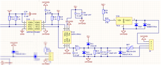
The first and second pins of the J9 terminal are the input terminals of the 4-20mA sampling circuit. The 4-20mA signal flows through the 120R sampling resistor of the circuit, generating a voltage at both ends of the resistor. ADS1100A1 collects this voltage and converts it into an I2C digital signal, which is isolated by ADUM1250 and communicates with the microcontroller. When terminals 1 and 2 of J9 are suspended (unloaded), the output signal of ADS1100A1 is at full capacity, i.e. FFFF, causing measurement abnormalities. When the J9 terminal is connected to the signal line, even if the output current of the signal line is 0A, the ADS1100A1 output data can still be 0 (i.e. 0000). However, when the 1 and 2 terminals of J9 are short circuited (i.e. not through external current input), the output is still at full capacity (FFFF)