This thread has been locked.

If you have a related question, please click the "Ask a related question" button in the top right corner. The newly created question will be automatically linked to this question.

ADS1299: Open circuit detection and capacitors effect on the lead-off excitation signal

Part Number: ADS1299

Tool/software:

Hi

We are doing some testing & preparing the algorithms for the Lead-off detection functionality

There is an anomality in cases where NOTHING is connected to the system (open circuit)

Theoretically speaking  - no circuit - no current flow, thus no signal.

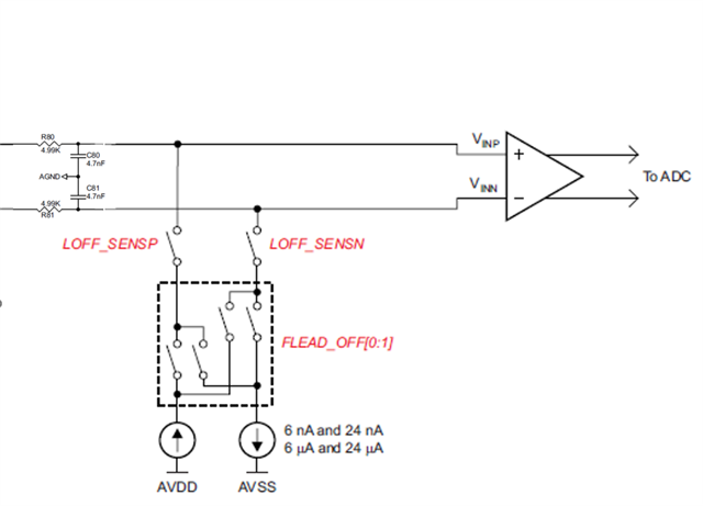
In practice there is an effect of charging the anti-aliasing filter capacitors of 4.7nF to AGND at low frequencies.

We expect it to be manifested in the form of a triangular wave with amp of about 40mV for a 24nA current settings at 31.2Hz (constant current charging of cap).

Could you please detail your practical experience with this phenomenon and the way you recommend dealing with the case of open circuit detection?

Do these capacitors force their charged voltage over the external impedance (since they are connected directly to the PGA)?

Thanks,

Ilan

  • The following schematic illustrates the capacitive effect:

    Calculated waveform (assuming separate charge/discharge of caps Vs AGND) for 24nA/31.2Hz:

  • Hello Ilan,

    Thank you for your post.

    The antialiasing filter caps will act as a momentary low-impedance whenever the lead-off current sources switch polarity, from +24nA to -24nA and vice versa. You'll see a brief spike in current through the cap as the voltage increases following an R-C time constant. At these typical values, the voltage should settle fairly quickly, resulting in a small amplitude voltage square wave switching at the lead-off current frequency. I would not expect to see a constantly charging/discharging waveform like the calculated results above.

    The amplitude of the lead-off waveform will be set by the impedance in the path from INxP to INxN. In the example simulation below, I've included 20kΩ of impedance per lead in addition to the filter resistors, resulting in a square wave of ±1.2mV with 24nA lead-off current.

    In the real application, the inputs should be biased by the RLD or BIAS amplifier to a nearly constant common-mode voltage. Below, I've set the RLDREF to mid-supply. The "V_CINx" meters are measuring the common-mode voltage of each input cap with respect to RLDREF to observe the voltage change due to the lead-off current.

    Regards,

    Ryan

  • Hi Ryan,

    Thank you for your detailed answer

    Could you please elaborate more on the case of open circuit (when the leads are not connected at all)?

    Would we have a signal which is bigger or smaller that high Lead impedance connected?

    I also noticed that using BIAS to reference the signal to appx zero is required. Could you explain what will happen if BIAS is not used ?

    Best regards,

                             Ilan

  • Hi Ilan,

    You make a good point. As the electrode impedance increases, the differential input voltage does become more triangular and the amplitude eventually saturates. Please see the attached PPT with the results summary.

    VIN vs R_ELEC with AC LOFF.pptx

    Bio-potential signals are electrically floating with respect to the measurement signal chain. Therefore, it is necessary to establish a common-mode voltage on the body and ensure those signals are within the acceptable range of the analog front-end circuit (typically near mid-supply). In addition, a dedicated BIAS amplifier will help improve CMRR performance of the system.

    Regards,

    Ryan