This thread has been locked.

If you have a related question, please click the "Ask a related question" button in the top right corner. The newly created question will be automatically linked to this question.

ADS122C04EVM: Reading temperature and connecting a wheatstone bridge

Part Number: ADS122C04EVM
Other Parts Discussed in Thread: ADS122C04,
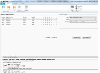
Tool/software:

I have been using another chip and a separate temp sensor for a medical weighing application.

However, I wanted to try out ADS122C04, and I got the evaluation board.

I have it connected to my SOC (nrf9160DK) via I2C. I do not seem to be able to get any sensible data.

This is the terminal communication I do:
i2c scan I2C_3
0 1 2 3 4 5 6 7 8 9 a b c d e f
00: -- -- -- -- -- -- -- -- -- -- -- --
10: -- -- -- -- -- -- -- -- 18 -- -- -- -- -- -- --
20: -- -- -- -- -- -- -- -- -- -- -- -- -- -- -- --
30: -- -- -- -- -- -- -- -- -- -- -- -- -- -- -- --
40: 40 -- -- -- -- -- -- -- -- -- -- -- -- -- -- --
50: -- -- -- -- -- -- -- -- -- -- -- -- -- -- -- --
60: -- -- -- -- -- -- -- -- -- -- -- -- -- -- -- --
70: -- -- -- -- -- -- -- --
2 devices found on I2C_3
-> The chip is found at 0x40 (the device at 0x18 is separate temp sensor for comparison)

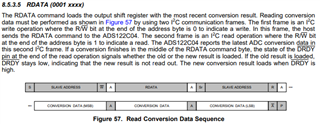
i2c write I2C_3 0x40 0x06 // reset chip
i2c write I2C_3 0x40 0x4C 0x10 // Setting TS bit to 1 (enable built-in temp sensor)
i2c write I2C_3 0x40 0x08 // Starting conversions
i2c write I2C_3 0x40 0x10 // Sending RDATA command
i2c read I2C_3 0x40 3 // Read data

I get 00000000: 00 00 00 00 00 00 00 00  00 00 00 00 00 00 00 00 |........ ........|

So clearly I am doing something wrong, but what?
The other temp sensor connected on the same bus gives correct results...

These are my immediate goals:
1) Get the internal temp sensor working
- Do I need to set the jumpers to something special (other than default on the board)?
- Are my commands correct?
- What do I need to do
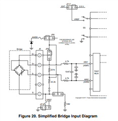
2) Connect my wheatstone bridge, set the gain to 128 and take a reading
- How/where do I connect my bridge to the evaluation kit (my bridge works on my HX711, but I not want to try this device)
- How do I correctly set the gain and set the other relevant parameters?


Sorry for the basic questions, but one has to start somewhere

  • Hi Bjorn,

    The I2C flow (reset chip, writing to the configuration register 1 to enable temperature sensor mode, start conversions, read conversion data) mentioned seems correct, make sure you are following the read conversion data sequence (shown below) stated in the data sheet properly.

    I can't comment on your terminal communication.

    What I would recommend is using a logic analyzer or an oscilloscope to monitor the digital communication when you issue your I2C commands.

    This helps verify that the digital communication looks correct as stated in the data sheet, or if there are problems with the way your I2C communication looks.

    This is what the I2C sequence should look like to read data from the device after setting your configuration (enable built-in temp sensor) and starting the conversions:

    1) Get the internal temp sensor working

    The temperature sensor mode is enabled by setting the TS bit = 1 in the configuration register. When in temperature sensor mode, the settings of configuration register 0 have no effect and the device uses the internal reference for measurement, regardless of the selected voltage reference source. Temperature readings follow the same process as the analog inputs for starting and reading conversion results. Temperature data are represented as a 14-bit effective result that is left justified within the 24-bit conversion result. When reading the three data bytes, the first 14 bits (MSBs) are used to indicate the temperature measurement result. The LSBs of the data output do not indicate temperature. Only the 14 MSBs are relevant. One 14-bit LSB equals 0.03125°C

    Reference section 8.3.10 of the data sheet for details on the internal temperature sensor. 

    - How/where do I connect my bridge to the evaluation kit (my bridge works on my HX711, but I not want to try this device)

    Please reference section 5.1.3 of the ADS122C04 user's guide for information on connecting a bridge to the EVM. 

    - How do I correctly set the gain and set the other relevant parameters?

    If you are using the ADS122C04EVM, you can download the EVM GUI from: ADS122C04EVM Evaluation board | TI.com

    Details on installation procedure with figures are available in the EVM's user's guide (section 4.1.1 onwards).

    The GUI will allow you to select your configuration and display data captures without having to write your own code for evaluation purposes.

    Here's a capture from the GUI where you can choose your parameters such as mux selection, gain, data rate etc. 

    If using your own controller/code, write to the appropriate registers through the I2C commands to set the gain and relevant parameters. Information on what to write to the configuration registers to set your desired parameters is available on section '8.6 Register Map' of the data sheet.

    Best Regards,

    Angel

  • Hello,

    I was able to get both temperature and strain gauge bridge working - finally!


    What is best practice for temperature compensation?

    Would I for example read the value of the internal thermistor from time to time?


    Bjorn

  • Hi Bjorn,

    It may be helpful to take a look at our Temperature-sensor (RTD, thermocouple, thermistor) firmware for precision ADCs: 

    ADC-TEMP-SENSOR-FW Application software & framework | TI.com

    This temperature-sensor linearization firmware provides a software routine for measuring and linearizing most common temperature sensors, including resistance temperature detectors (RTDs), thermocouples, thermistors (NTC, PTC, etc.) and analog temperature sensors.

    I also suggest taking a look at our app note: A Basic Guide to Bridge Measurements (Rev. A) (ti.com), for additional information on bridge measurements.

    Best Regards,

    Angel