This thread has been locked.

If you have a related question, please click the "Ask a related question" button in the top right corner. The newly created question will be automatically linked to this question.

ADS1115: Research ADC for precise measurement Volts 4 lithium batteries

Part Number: ADS1115
Other Parts Discussed in Thread: ADS1119

Tool/software:

Hi everyone.

I'm looking for a simple to use chip that allows me to read only the precise voltages of 4 lithium batteries in series with each other (in 4S configuration as shown in the image)

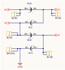
I'm looking for a high precision ADC that allows me to only take voltage readings on 4 lithium cells placed in series (in 4S configuration as shown in the image) and that communicates with the ESP32 through the i2c protocol.
It is difficult to find a chip that only does what I require (for example, I have seen that these functions are present in battery charging chips, but since they are already in an advanced stage of the project it would mean having to start from the beginning with a good part of the work); so it could be that what you suggest also has other features, but if there was something that was limited to just doing what I need it would be excellent because the size and complexity of the package would be reduced.

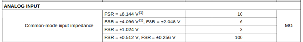
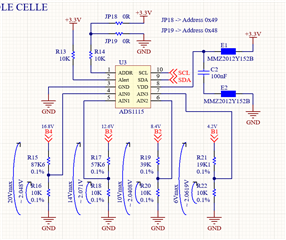
I have now tried with an ADS1115 module which is 16bit, the problem is that its use to read the battery voltages is necessarily linked to voltage dividers and for other factors I need the Battery- to coincide with the GND of the whole rest of the system.

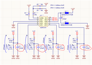
Currently the ADS1115 that I use is composed as follows but, I think due to the dividers (although all resistors are 0.1%) the voltage readings are not so precise compared to those read on the voltmeter (for example 16.72V on the voltmeter appears to be on the 'ADS1115 16.56V) and this with lithium battery is not a good thing as they are batteries for which you have to be careful of the voltages involved.

Do you have any other suggestions for getting the 4 accurate battery measurements?
Thank you


Gaggero

  • Hi Paolo,

    The schematic makes sense, and it seems to me that you should be able to get reasonable measurements with it.

    Have you built a circuit board for this schematic, or are you testing in on some sort of breadboard / fly-wiring the connections?

    What multimeter are you using for corroborating your results?

    The reason I asked about the multimeter is that if your measurement doesn't match the ADC, one or the other is in error. If you use a cheap handheld meter, then I'd guess that the meter has some significant offset and gain error. Additionally, the input impedance of the multimeter is rather low, so the resistance it sees from the voltage divider will be off because of loading. If you have a precision multimeter (like an Agilent 34410A or 3458A), then I would use that as a good check of the ADC accuracy. These meters will have settings to increase the input impedance, so the measurement doesn't load the circuit. Using a precision multimeter in parallel with the ADC shouldn't affect the measurements.

    Your measurements do seem to be in the same 'ballpark", so it is worth it to corroborate that the difference in measurement isn't caused by the use of your equipment.

    Best Regards,

    Angel

  • Hi Paolo,

    It is possible that you might just need to perform an offset and gain calibration of the ADS1115, and that would get your values to align.

    You may also consider taking a look at the ADS1119, which should offer slightly better performance, but would typically still require calibration.

    Best Regards,

    Angel

  • HI Angel. Thanks for your answer.
    So as a voltmeter I used both the Tacklife (which has never missed a beat and therefore seems strange to me) and the recently calibrated Fluke that we have in the company and for both the values ​​differed very little.
    So you're saying that I will have to calibrate the ADS1115 by putting a formula in it that gives me the value returned by the ADS1115 equal to that read by the voltmeter?
    So for example by inserting a constant? That is, if the voltmeter reads 16.72V and the ADS1115 reads 16.56V will I have to multiply 16.56V x 1.0096618357... to ensure that it gives me the real value? You mean this?
    But will the result be linear for all values? That is, if the ADS1115 gives me 15.02V in the future, does it mean that it really will have 15.02V or could it mean that perhaps in reality I have 14.96 or another value due to a non-linearity of the ADC?

  • Hi Paolo,

    Please take a look at our series: Precision labs series: Analog-to-digital converters (ADCs) | TI.com

    The following video talks about the offset and gain and goes over an example of how to perform a two-point calibration. 

    Another possible suggestion that came to mind: 

    Rather than having four different ratios for the voltage dividers, could it be more accurate to divide all voltages down by the same amount (e.g. factor 4 or 5) and then measuring differentially between the resistor divider outputs?

    Best Regards,

    Angel

  • 16.72 V through 10/97.6 implies 1.7131 V at the ADC pin
    16.56 V through 10/97.6 implies 1.6967 V at the ADC pin

    So measure at the ADC pin. Is it closer to 1.6967 V or 1.7131 V?

    If the ADC pin is at the wrong voltage, you probably have an input impedance problem:


    If you don't want to use a bunch of buffer amplifiers, you could add some capacitance across the lower resistors on your divider.  Since battery voltages aren't rapidly changing anyway.


  • Hi Mark, so are you suggesting putting capacitors in parallel with the resistors of the dividers? In this way? And of what value? Would 100nF be ok?

  • Hi Paolo,

    Adding capacitors this way will act as an RC lowpass filter to the inputs of the ADC and will help filter out any higher frequency noise in your measurement.

    I'm not too sure if it would do much in regards to making the ADC readings match your FLUKE readings. 

    In regards to the input impedance, the lower the resistance values of your voltage divider, the less the input impedance affects the measurement, but having high value resistors would cause a more significant change.

    You can think of the input impedance as being in parallel to the lower resistor of the divider, so at FSR = 4.096V, input impedance = 3MΩ, it would be like having a 9,966.7Ω resistor instead of a 10kΩ, (10kΩ*3MΩ / 10kΩ+3MΩ).

    Best,

    Angel