TLA2518: Lack of Channel Data when Appended

Part Number: TLA2518
Other Parts Discussed in Thread: TLA2528

Tool/software:

Hi TI Team, 

Following my last post regarding my unresponsive TLA2518, I have successfully corrected the issue.

Now I am receiving data but despite correctly setting the registers for Auto Sequence and Channel Append, I am not receiving a correct channel update.

The TLA2528 channel append worked really well but I can't get it to function on the TLA2518.

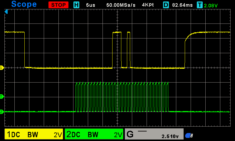
Here is the output from setting up the device.  Can you see anything wrong with these register settings?

** Monitor Output **

TLA2518 ADC2 started

All Pins Set to Inputs
Channel Append Added to Result
OSR Register =:11
Sampling Speed set to 160 SPS & Oscillator set to Low Power
All Pins added to Auto Sequence
Auto Sequence Started
System Status ADC2 = :11000001
ADC2 Configuration Complete

ADC2 Config =:
-------- TLA2518 --------
System Status = 11000001
General Config = 0
Data Config = 10000
OSR Config = 11
OP Mode = 11111
Pin Config = 0
GPIO Config = 0
GPO Drive Config = 0
GPO Value = 0
GPI Value = 0
Sequence Config = 10001
Manual Channel Select = 0
Auto Sequence Channel Select = 11111111
-------- TLA2518 --------

Battery Voltage =: 10011000110
Channel =: 101                                   **Should be AIN0**
Battery Voltage =: 1111111000110
Channel =: 101                                   **Should be AIN1**
Battery Voltage =: 1111110001000
Channel =: 101                                   **Should be AIN2**
Battery Voltage =: 11011100000
Channel =: 101                                   **Should be AIN3**

In addition to the channel ID error, the reading above is also incorrect in that I expect with 1.1VDC on AIN0 (DVDD & AVDD = 5VDC), a reading of 14,418 or 0011100001010010 (16 bits due to OSR being on) should be presented.  I am also expecting the 4 bit channel ID to occupy bits 16-19.  I'm reading the value into an array that is 3 x 8 bit elements long so array element 0 & 1 will have the data and element 2 has the channel ID.  The channel ID needs bit shifting 4 bits to the right to make it correct.  Code is pretty straightforward.  Is it possible that I'm getting the data out as LSB first, through to MSB?  My understanding of the chip manual and the ESP32 SPI implementation is that it should be giving MSB first?

Should I wait for the SYSTEM_STATUS OSR_DONE bit to be set before trying to read the data?  I didn't need to do this with the TLA 2528 so haven't implemented it.

The main reason for the question is that as I'm able to set and read registers OK, my understanding of the SPI comms seems sound.

  • Hi Jason,

    I'm glad you were able to solve your previous issue. Figure 25 of the datasheet is index 1. Following this, 16-bit averaged data takes up bits 1-16, and the Channel ID takes up bits 17-20. If your array is index 0, then you are correct. The data for the TLA2518 would come out MSB-first as you expected. Currently, we don't have a goo understanding on the OSR_DONE bit will toggle on, so I wouldn't recommend implementing that in your code. 

    To isolate this issue from anything going on within your code, are you able to send a logic capture or oscilloscope capture of the 20-bit data transmission you are getting? Are you also able to read from the CHANNEL_SEL register to see what channel value it is currently set to before you get your data back?

    Regards,
    Joel

  • Hi Joel, 

    Thanks for the response.  Its good to know my basic understanding is correct.  I've prepared a pdf showing the first 4 captures (4 screen shots) from the device but I can't see how I could attach it to the post?  What is the best way to attach a file?

    I can confirm that despite:

    -writing 0b00000000 to PIN_CFG_ADDRESS, setting all pins as analog inputs AND

    -writing 0b00010000 to DATA_CFG_ADDRESS, turning on Channel Append

    -writing 0b11111111 to AUTO_SEQ_CH_SEL_ADDRESS, adding all pins to the auto sequence

    -writing 0b00010001 to SEQUENCE_CFG_ADDRESS, starting the auto sequence process.

    , the channel append is not working and only returns channel 2.  Additionally, the first sample returned is not AIN0, it is AIN3.

    Here is the full setup sequence of the chip:

    All Pins Set to Inputs
    Channel Append Added to Result
    OSR Register is set to OSR 128
    Sampling Speed set to 160 SPS & Oscillator set to Low Power
    All Pins added to Auto Sequence
    Auto Sequence Started
    System Status ADC2 = :11000001
    ADC2 Configuration Complete

    Input Sample screen shots below.  The ESP32 SPI.h only allows 8bit, 16bit and 32bit transactions so I'm stuck with 32 bits to read the 20 bits I need. (hence the 32 SCK clocks.  Bit shifting 12 places to the right removes the trailing 0's easy enough.

    First Sample:

    Second Sample:

    Third  Sample:

    Fourth Sample:

    Please let me know if you need anything else.

    Regards

    Jason

  • Just to add, I've just cold restarted my board (not a warm reboot) and have found that the channel output has changed.  Currently the chip is outputting Channel 5.  Another restart, I get channel 8.  The analog values haven't changed at all, just the channel number.  Warm restart keeps channel 8 for all analog reads.

    Thanks,

    Jason

  • Hi Jason,

    If you click Insert > Image/video/file under the comment box, you can attach whichever files you want. If it is not supported, you can also attach a .zip with them included.

    Apologies for the delay in response. Can you expand on the conditions of your cold restart? Do you mean to say you are removing power completely from the ESP32 and TLA2518? And by warm reboot, you mean restarting the device in software? Let me know if I have that right. 

    Additionally, are you able to take captures of all 4 SPI pins labelled? If you have a logic analyzer that can export an interactive file, such as a Saleae, even better. I'm just trying to get a clearer picture of what data is coming out from the ESP32. Please let me know if you have any breakthroughs in the meanwhile.

    Regards,
    Joel

  • G'Day Joel, 

    Yes, cold restart removed power from the chip and the ESP32 and restarted it, complete with resetting all the setup registers.  Warm restart just resets the ESP32, so the chip is software reset and then re-setup.

    Cold restart results in the channel number changing.  Warm restart results in the channel number staying the same.

    So the breakthrough is that I have gone back and checked my board layout and I have discovered that pin 17 (ground plane) is disconnected from GND (Pin 9) Disappointed

    Here is the updated layout that is pretty close to that on the data sheet.  Still, its hard to get every input to not cross over but I'm not going for high speed sampling either.

    I'll get a new board made and see how I go.

    Thanks

    Jason

  • Hi Jason,

    That's unfortunate, but it's great that you were able to pinpoint the problem! I'm sure that the issue you're seeing should be resolved with the new board. Feel free to open this thread up or start a new one if you have any further issues.

    Regards,
    Joel

  • Hi Joel, 

    I'm pleased to announce the new board has resolved the issue.  Thanks for all your help Slight smile