This thread has been locked.

If you have a related question, please click the "Ask a related question" button in the top right corner. The newly created question will be automatically linked to this question.

DAC63204: _

Part Number: DAC63204

Tool/software:

Hi,

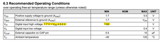
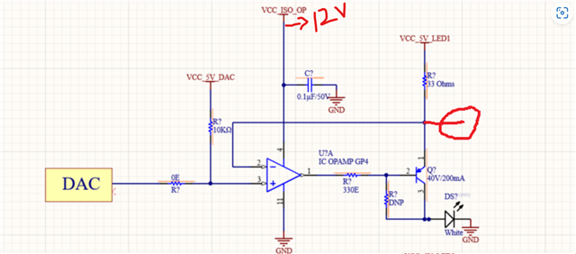
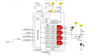
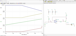
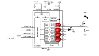
I have planned to use DAC63204 for led brightness control in my design. The microcontroller that is used functions at 3.3v. Will it be possible to power DAC63204 at 3.3v to avoid the usage of  level translators for I2C and SPI?

Thank you.

Regards, 

Jeevan

  • Jeevan,

    Yes, the DAC63204 can be powered with 3.3V. Any VDD 3.3V or above would be compatible with 3.3V logic for the DAC63204 as the VIH and VIL thresholds are not dependent on VDD:

    Best,

    Katlynne Jones

  • Another comment, if you power the DAC with 3.3V, the maximum output voltage possible is 3.3V. 

  • Hi Katlyeen,

    Thank you for the swift response.

    I am planning to replace the existing DAC with the DAC63204. The reference schematic for the current design is similar to the attached design (constant current source). While trying to understand this design, I seek your help to determine whether the DAC63204 can be used with a 3.3V VDD, or if a 5V VDD is necessary.

    Thankyou.

    Regards,

    Jeevan

  • I took reference from the evaluation board and am trying to implement something similar to this.

  • Hi Jeevan,

    I assume you're interested in controlling the LED current from 0mA to some maximum value. When I simulate your circuit with a standard op amp and PNP, I get the following:

    Using a 3.3V DAC VDD will slightly change the output range:

    You'd have to adjust the scaling resistor to get the range you want.

    Best,

    Katlynne Jones

  • Hi,

    I am interested in varying the current to the LED from 0 mA to 80 mA, so I am setting the value of Rset to 12 Ω. The forward voltage of the LED is 3.23 V, and I am using a separate LDO to power the DAC (5 V) and VDD for the LED to avoid voltage drop. Is this fine?

    Thankyou.

    Regards,

    Jeevan

  • Hi Jeevan,

    In the future, can you paste your images directly in the post? It is trouble for us to access file sharing sites. 

    Or are you using I2C and connecting A0 to ground? If you're using SPI, make sure R10 not populated.

    This will work but you're losing out on a lot of the DAC range. You'll only be able to operate form ~4V to 5V which is only 20% of the range. 

    Here's the sim if you would like to play around with it. LEDBiasE2E.TSC

    Best,

    Katlynne Jones

  • Hi Katlynne,

    Noted, will directly paste the images in the post. We have given the provision for both i2c and SPI.A0 is connected to the ground for i2c address selection. I am unclear about why the output range is reduced. Is it due to the forward voltage of the LED, or does it depend on other factors? What should be done to increase the range?

    A special thanks for the simulation file.

    Regards,

    Jeevan

  • Hi Jeevan, 

    If you look at the sim screenshot, the DAC output only has an effect on the LED current from about 3.9V to 5V (VDD). Yes, this is due to the forward voltage of the LED (which I've shown as a 3.3V voltage source in the sim), and also the base and collector diode drop of whatever BJT you're using (about 600mV in the one I used in the sim).


    The only way to increase the range would be to use an LED with a smaller forward voltage and BJT with a small b-c drop. Alternatively, you could bias the LED as shown in this figure. Some people do not like it because the LED is on the high side, but you get to use a lot more of the DAC range.

    High-Side Current Source LED Biasing Circuit Using Smart DACs

    Best,

    Katlynne Jones

  • Hi Katlynne,

    I hope you are doing well.

    I have been working on the schematics of the DAC and would like your expertise on the following:

    1. According to my understanding of the design using a PNP transistor, IBI_BIB is calculated by subtracting the DAC's output voltage from the emitter-base voltage and dividing by the base resistor ((VEB−VDAC)/330Ω(V_{EB} - V_{DAC}) / 330Ω(VEBVDAC)/330Ω). Is this correct, or does IBI_BIB depend on the output current from the DAC (op-amp output)?

    2. The logic high and low voltages of the DAC are 1.62V and 0.4V, respectively, while those of the controller are 1.7V and 0.825V. Following the evaluation board of the DAC, I have used a translator for I2C and SPI since the DAC operates at 5V and the controller operates at 3.3V. Is the translator necessary?

    Thank you!

    Regards,

    Jeevan

  • Hi Jeevan,

    1. You're correct in calculating the current. The DAC output buffer will source/sink as much current as you've calculated up to around +/-5mA. Past that, the buffer will not be able to regulate the output. 

    2. The level translator is not necessary in your case. If the controller logic level was higher than the DAC VDD then you would need the translator. 

    Best,

    Katlynne Jones

  • Hi Katlynne,

    1. I was not able to find any absolute maximum current mentioned for xOUT, can the xOUT handle 5mA?

    2. For the same, when using SPI since it uses a push-pull configuration will translator be required? The Controller which is being used only supports 4 wire SPI mode.

    Thanks & Regards,

    Jeevan

  • Hi Jeevan, 

    1. Yes, 5mA will be fine. We have this plot to show that the device has great load regulation up to +/-5mA. The device can do more than that, but you'll likely see a small drop in output voltage around 8mA - 10mA. And a more significant drop past 10mA. The device has a short circuit limit of 60mA for a 5.5V VDD, so you can consider this to be the max if you were to short the output to VDD or ground. 

    2. The DAC would only ever drive the SDO pin which is an open drain output pin. Connect a pullup resistor on this pin to your 3.3V controller supply. SCLK, SYNC, and SDI are only input pins on the DAC, so they will never drive a 5V output that could damage your controller. 

    Best,

    Katlynne Jones