Other Parts Discussed in Thread: ADS1299,
Tool/software:
Hello everyone.
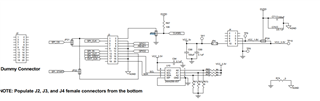
I want to use ADS1299 to develop EEG devices. So I bought ADS1299EEGFE-PDK, which I think is easier to use. I want to control it with STM32 processor. I would like to ask, is it feasible to connect the test board to MMB0, powered by MMB0 and controlled by stm32?
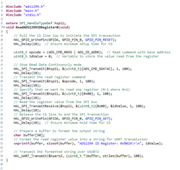
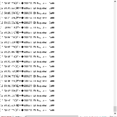
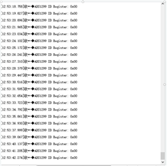
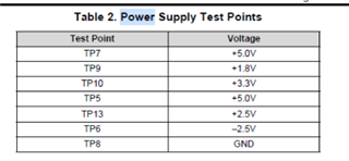
But I seem to have encountered some problems and I am troubleshooting. I can't read the default register value of ADS1299 on the test board through SPI instructions. I'm not sure if I damaged the board. I want to know if there is any way to verify that the board is intact? Can I judge whether the board is intact by the voltage of these TPs?
Current jumper configurations:
JP1: open
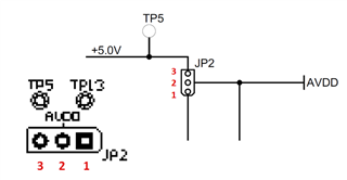
JP2: 2-3
JP4: 1-2
JP6: 1-2
JP7: 1-2
JP8: 1-2
JP17: open
JP18: 2-3
JP19: 1-2
JP20: 1-2
JP21: 1-2
JP22: 2-3
JP23: 1-2
JP24: 2-3
Is there anything glaringly wrong with this setup?
Also, I want to know, when I want to use the 2.048Mhz crystal on the ADS1299EEGFE-PDK board, how should I set the jumpers JP18 and JP23?
The JP18 should be 2-3, JP23 should be 1-2?
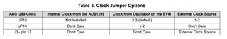
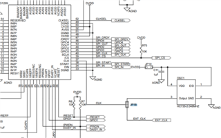
But in the circuit diagram, if JP18 is connected as 2-3 (The middle and lower terminals of the three terminals), does it mean that EXT_CLK is used?
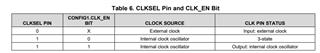
And I also want to know, ADS1299 is using internal crystal, crystal on EVM, or external crystal. Will different crystal frequencies affect SPI communication?
Thanks a lot for it.