This thread has been locked.

If you have a related question, please click the "Ask a related question" button in the top right corner. The newly created question will be automatically linked to this question.

ADS1291: Just two electrodes - AC Coupling and RLD loop

Part Number: ADS1291

Tool/software:

Hello TI,

I have some doubts related to the ADS1291 only using two electrodes. I found in some discussions that for this purpose it is needed to AC coupling the inputs and including the RLD loop.

I developed the following circuit:

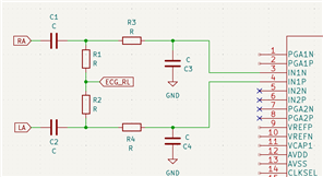
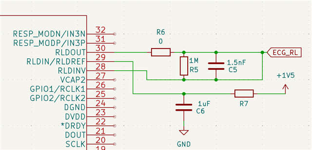
Is this correct? Could someone explain the funcionality of the RLD loop? 

Thanks!

  • Hello Pablo,

    The basic scheme in the first image looks correct. If it is helpful, I can reach out to you offline and review the complete the schematic once component values have been selected.

    Traditionally, the RLD amplifier is used to establish a DC bias voltage on the body such that bio-potential signals are referenced near mid-supply of the analog front-end circuitry (i.e. the PGA inputs). In addition, the RLD can help to suppress common-mode noise interference, such as 50/60 Hz power line noise. Applications which do not use a dedicated RLD electrode usually AC-couple the inputs and establish the DC bias on the PCB with a pull-up resistor to mid-supply or with a resistor divider between + and - supplies.

    Regards,

    Ryan