This thread has been locked.

If you have a related question, please click the "Ask a related question" button in the top right corner. The newly created question will be automatically linked to this question.

ADS131M08EVM: GUI Sample rate not accurate in low power mode & very low power mode

Part Number: ADS131M08EVM
Other Parts Discussed in Thread: ADS131M08

Tool/software:

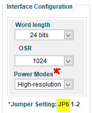
Using the ADS131M08EVM software, and things are good in the high resolution mode.

I am able to hook up a function generator, and measure the 100Hz sine wave I'm generating, and see the FFT.

When I change to low-resolution mode, the sample rate goes down 1/2 which was fine initially.

However the time domain wave is unexpectedly the same when it should be elongated, so it appears the sample rate in hardware is actually not changed.

The frequency domain's fundamental frequency is divided by 1/2, reporting a 50Hz wave, despite no change to the FGEN 100Hz output.

Essentially, low power mode is giving me half of the expected frequency, and I believe there's some software issue with this.

I also suspect very-low power mode divides the frequency by another 1/2, ie going to report to me a 25Hz wave when the FGEN is generating 100Hz.

  • Hi Orlando,

    If you keep using OSR=1024 configuration while switching the mode, the half output data rate is expected, you can check the Table 8-2. OSR Settings and Data Rates for Nominal Master Clock Frequencies in the ADS131M08 datasheet.

    The waveform in the time domain wave shows the period time per cycle which is your input signal frequency, it is not ADC's data rate.

    The 50Hz fundamental frequency shown in the frequency domain is not correctly calculated. If you look at other output parameters in in frequency domain, they all show 'NaN', which means the GUI could not correctly calculate those parameters. You should increase the number of samples collected by the GUI.

    BR,

    Dale

  • Hi Dale,

    I understand with the same OSR the sample rate must be reduced. I expected this.

    Ignoring the sample rate, my input waveform has periodicity of 40 samples in both cases.

    40 samples is expected for 4kHz fs. (4kHz/40 = 100Hz).

    However it is not expected for 2kHz fs. (2kHz/40 = 50Hz). I should be seeing periodicity of 20 samples.

    That's the core of the issue.

    I'm not sure if the software is configuring the clock register correctly, because the ADC data rate seems like it's not changing.

    I don't need an immediate resolution, just reporting an issue I'm finding with this, not sure if its software or hardware.

    I don't plan on using the GUI in my application, just doing some initial testing. 

    I'll branch this to a new thread if I find issues when using my own interface. 

    Thank you kindly Dale.

    -Orlando

  • Hi Orlando,

    I just double checked it with a logic analyzer, the actual data rate is still 4ksps after switching to Low-Power mode or Very-Low-Power mode in the ADS131M08 GUI without other changes as shown in the following screenshot.

    BR,

    Dale 

  • Hi Orlando,

    I just talked to my colleagues in out team, and also checked the ADS131M08EVM user guide and the datasheet. When you switching the mode in the GUI, a different master clock frequency is expected by the ADC, e.g.  8.192 MHz clock frequency is expected for the high-resolution (HR) mode, 4.096 MHz clock frequency is expected for the low-power (LP) mode, and 2.048 MHz is expected for very-low-power (VLP) mode, the external clock frequencies can be changed by installing a jumper in the appropriate position on the JP10 header on the ADS131M08EVM, these information are mentioned in the section of 2.2 ADC External Clock (CLKIN) Options in the EVM user guide and also in the table 8-2 in the datasheet.

    The GUI itself can not detect whether the external master clock is properly changed or not, so the calculation for all the parameters is related to the mode you selected in the GUI. If you did not properly change or select the external clock frequency, you will see half data rate calculated by the GUI and also incorrect calculation for the input signal frequency, so this is not the issue in the GUI software.

    I hope my explanation is clear. Thanks!

    BR,

    Dale

  • Dale, 

    Perfect. I haven't tested it, but I understand how this should correct things.

    Maybe a fix for next revision, correct GUI's JP6 to JP10.

    Also an asterisk after Power Modes will further clarify that the Jumper is relevant there.

    Thank you!

  • Hi Orlando,

    These can be updated when we have a chance in the future, thanks.

    BR,

    Dale