This thread has been locked.

If you have a related question, please click the "Ask a related question" button in the top right corner. The newly created question will be automatically linked to this question.

ADC3683EVM: Access to 20-bit mode GUI selection and bit deserialization using FCLK phase

Part Number: ADC3683EVM
Other Parts Discussed in Thread: ADC3683

Tool/software:

I use the ADC eval board (ADC3683EVM).My plan had been to use the control program provided by TI (ADC35XXEVM GUI, as laid out in "sbau360.pdf" user guide). I require the use of the 20-bit 2-wire mode available on ADC3683. However, the control program only gives options 14, 16 and 18 bits. So, I have a couple of questions:


1) Is there another ready-to-use control program provided by TI (or a 3rd party) that gives access to the full range of features of ADC3683? Perhaps I can gain access to the source code of the program so we could ourselves add features that we need?


2) (in case there isn't another GUI-based program) It appears that the control program operation behind the scenes is simply a collection of register reads and writes over USB, so perhaps you can point me to a piece of software (again, from TI or in public domain) that would provide a simple register read/write interface (over USB using the on-board FTDI chip) compatible with the ADC3683EVM? I imagine that internally to TI you guys must have something to access the full set of features of your ADCs installed in eval boards (?).

3) The GUI program provides an option to load a Python file, but there is no mention of this functionality in the user guide. I imagine this feature may allow a general control over the ADC functions, but I'd need to know the nature of the Python script the program accepts. For example, can it just be a list of "reg_write" and "reg_read" operations, and, if so, it would be nice to have the description of the python libraries available to the user and how to use them. There is also a "register read" and "register write" boxes. Can they be used to augment the settings not otherwise available through the GUI selection menus?
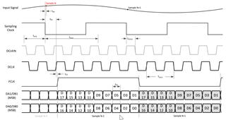
4) phasing of FCLK with respect to the "previous sample" and "current sample" is not clear from the ADC3683 user guide: when performing de-serialization in the receiving device, is there an assumption that FCLK is high during the "previous sample" and low during "current sample" (or vice versa)? Otherwise, how can the received serial bit values be correctly mapped back to the original parallel binary sample values?
  • Hi Maxim,

    1)No, there is not another program or option.

    2/3)Outside of developing python code to send and read SPI signals over the FTDI chip, the best way to program this use case is to load a .txt file. I have attached a .txt file for 20b bypass mode configuration in the correct format (which is register address, tab, register data).

    4)Yes, FCLK is high during the previous sample and low during the current sample.

    20bit_2wire_bypass.txt
    //Reg Data
    
    //2 wire bypass
    0x00	0x01
    0x00	0x00
    0x07	0x4B
    0x13	0x01
    0x13	0x00
    0x19	0x10
    0x1B	0x40

    Best regards,

    Drew

  • Thank you Drew for your reply. One follow-up question: where in the ADC35XXEVM GUI program does it let me to load a text file in the format you've provided ( I assume you meant for me to use that program to talk to the ADC board over USB)? I see a "Load" button, but it prompts for a ".py" file type - not plain text. Is this the menu to load ".txt" files from as well? Thank you

  • Hi Maxim,

    Yes, the Load Config button is where you would load the .txt file. To confirm if it is working, you can clear the log and then upload the file. If the log populates with writes, then it was read into the GUI.

    Best regards,
    Drew