ADS131M02: ADC always reads 0x8000 no matter what the input analog signal is

Part Number: ADS131M02

Tool/software:

Hello,

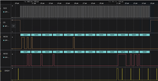
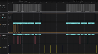
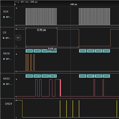
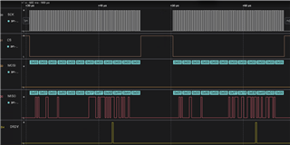
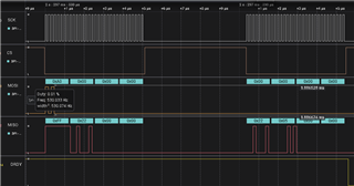
I'm able to correctly read the chip ID register and also set the ADC mode to 16-bit correctly as seen in the scopeshots provided below:

Chip ID: Gives me 0x22XX

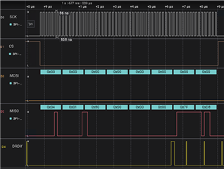
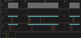
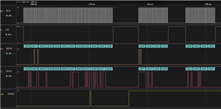
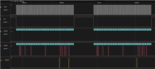
I have disabled Ch1 and only trying to read Ch0. Here's what I get when I send the NULL command:

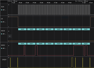
As you can see in the response, the DRDY0 bit is set, the Ch0 reads 0x8000 and Ch1 reads 0x0000. 

No matter what I do, the CH0 always reads 0x8000. I even tried using the internal positive DC test signal and I still get the same value. What am I doing wrong?

Regards,

Dheeraj

  • Hi Dheeraj,

    welcome to our e2e forum and thanks a lot for choosing a TI ADC.

    From the scope shots you showed and your explanations, you don't seem to do anything wrong at first sight.
    Can you try the following things:

    • Set MUX0[1:0] = 01b.
      In this case you should definitely see the conversion data change.
    • Send the STANDBY command first before making any register bit changes.
      Change the register bit settings.
      Send the WAKEUP command to start conversions with the new register settings.
    • Have you verified your WREG command is working by reading back the register settings using the RREG command?
      As you seem to be able to change the word length, I suppose the WREG command is okay.

    Regards,
    Joachim Wuerker

  • Thanks for helping me with this.

    Here's me trying to set the MUX[1:0] to 01b.

    Verified my write to make sure it is 0x01. See the response frame on the right.

    Here's what I read on the ADC. Again the same result of 0x8000. 

    Here's me sending the Standby and Wakeup commands before writing the Ch0 config register. But I did this for every register write as well:

    Verified that the channel config register is set correctly:

    Even with this the result of the ADC is 0x8000. Same scopeshot as before.

    Yes, I have verified the register settings after each write. 

    Thanks in advance.

    Regards,
    Dheeraj

  • Hi Dheeraj,

    thanks a lot for your additional measurements.
    Is it possible that you send the RESET command instead of the STANDBY command? Or did I misread this?

    In any case, maybe we should start from the very beginning to see where things might go wrong.
    Could you reset or power-cycle the device, and then just send a 3x24x4bit = 288bit frame with DIN held low? We should see data on Ch0 and Ch1 then which is different from 0x800000 or 0x000000. Send multiple frames with DIN held low to see if the data keeps changing.

    Once that is working, you can send the STANDBY command, then configure the device for 16-bit word length, etc. and then send the WAKEUP command.

    Also could you share the schematic of the design to make sure there are no issues?

    Regards,
    Joachim Wuerker

  • Good catch. I'm actually sending the standby command, but seems like for this particular transaction, it was sampled incorrectly. There is a 0.3-0.5% error in the clocking but should be nominal.

    Here's me trying a reset and reading the chip ID register to verify the ADC is working fine:

    And right after this, I'm reading the ADC data. Did you mean 3x8x4 = 96 bit frame? Please confirm. 

    Here again I see the data to be 0x800000 for both channels. 

    Regards,
    Dheeraj

  • Here's the schematic:

    And these are the differential signals going into the ADC inputs:

    Hope this helps!

    Regards,
    Dheeraj

  • Here's something interesting that I noticed. If I send the 96-bit frames 20 times, I see CH1 giving me some data a few times (20%). CH0 seems to be stuck at 0x800000. 

    Regards,
    Dheeraj

  • Hi Dheeraj,

    yes, of course 3x8x4bits = 96bits. What were I thinking :-).

    Thanks for sharing the schematics. I don't think it is the root cause of this problem, but both the AVDD and DVDD supply are expecting a 1uF cap to GND.

    Without changing anything else after reset, can you again change MUX0[1:0] = 01b and MUX1[1:0] = 01b and then just read data?
    It should be okay to change the multiplexer setting without going to Standby.

    Have you already tried a different board or unit to see if the problem exists on all boards?
    What input signals have you applied in your case?

    Regards,
    Joachim Wuerker

  • Hello

    I ran it on a different board. In this board, I see the values 0x8000 for channel 0 and channel 1, but occasionally I see data changing for channel 1 only. Is the value 0x8000 the default value returned by the ADC or something? 

    Currently I'm not making use of DRDY interrupt. I was trying to get this to work without it. Since the response word has the data ready bits set, I was hoping the ADC values are being read correctly. Is this not true? Should the data reads only be done on the falling edge of the DRDY interrupt?

    Let me know.

    Regards,
    Dheeraj