This thread has been locked.

If you have a related question, please click the "Ask a related question" button in the top right corner. The newly created question will be automatically linked to this question.

ADS1299EEGFE-PDK: ADS1299EEGFE-PDK

Part Number: ADS1299EEGFE-PDK
Other Parts Discussed in Thread: ADS1299

Tool/software:

Hi,

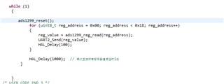
There seems to be a problem with the ID register of my test board, its value changed to 0xDF instead of 0x3E, I tried to fix it, I reconnected the power supply, but it didn't seem to work. I tried to reset it in TI's software, but the value I got was still 0xDF.

I wonder why? But when I read and wrote to the other registers, I was able to execute correctly. Do I need to fix this issue? Does it affect the data conversion features I want to use next?

Regards

Junzhe

  • Hi Junzhe,

    Thank you for your post.

    Can you try pulsing the /RESET pin while supplies remain on? Refer to section 11.1 and Figure 76 for relevant timing specifications. After completing the POR sequence, can you re-read the ID register and compare the result?

    Regards,

    Ryan

  • Hi Ryan,

    Thanks for your reply, I added a RESET instruction in my code and then read all registers, but the value of the ID register is still 0xDF.

    I have attached my code and a screenshot of the logic analyzer. The first picture is my code, I added the RESET instruction, the second picture is a screenshot of my logic analyzer, I sent the RESET instruction 0x06. Channel 3 is DIN, the third picture is a screenshot of my entire logic analyzer, after sending a RESET instruction, I read the 24 registers in sequence. Sorry I can't enlarge it, but I checked it for correctness, the fourth picture is the register value received by my serial port, except for the ID bit, everything looks normal.

    I don't know when the value of the ID bit changed, and I don't seem to have a way to restore it to normal, but it doesn't seem to affect my other operations. Can I ignore this problem?

    Regards

    Junzhe

  • Hi Junzhe,

    I agree that it appears everything else looks normal and the device should function as expected. You can proceed with evaluation for now.

    My suggestion was to toggle the nRESET pin, not to use the SPI RESET command. Can you try this according to section 11.1 and let me know if it makes any difference?

    Regards,

    Ryan

  • Hi Ryan, 

    I used the RESET pin in J3 on the ads1299EVM to reset it. I sent a low level to the RESET pin as required, but the value of the ID register did not change. I don't know if this is due to damage, but other functions are not affected. I saw other people asking similar questions in the forum, but there was no particularly good solution. In addition, I always thought that after the ads1299 is powered off, all registers will return to the initial value. This should not be due to initialization problems that cause the value of the ID register to change. This may be due to damage or other problems, but this problem may not affect other functions.

    Regards,

    Junzhe

  • Hi Junzhe,

    Thank you for trying it. Yes, after power-down, all registers will return to default. The ID register value is loaded at power-up from a one-time programmable (OTP) bit field. Sometimes, this OTP value can be read incorrectly by the ID register if power supplies ramp slowly. That is why it is always good practice to toggle the reset pin after power supplies have fully ramped. This reloads the OTP again and rules out power-up issues.

    Can you share the other posts which reference the incorrect ID? I will document this and have the team look into it. Otherwise, I think the device is functioning as expected and is not damaged. You can proceed with your evaluation.

    Regards,

    Ryan

  • Thank you, Junzhe. That is helpful. I will submit the feedback to have this validated and updated in the data sheet. I think you are ok to proceed with the Design ID value 0xDF.

    Regards,

    Ryan