This thread has been locked.

If you have a related question, please click the "Ask a related question" button in the top right corner. The newly created question will be automatically linked to this question.

ADS1299: Original waveform problem

Part Number: ADS1299

Tool/software:

TI Engineer

Hello!

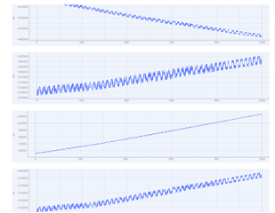
I used 1299 to build a 16-channel EEG acquisition system, and found that the waveform collected by the channel was slanted, and the original AD value was slanted, without any processing. What is the reason? Below is the waveform diagram, sampling motor, reference electrode, drive electrode are all empty (not carried on the head)
  • Hello Jiahao,

    Thank you for your post.

    With all input electrodes floating, what you are observing is likely a DC drift of the input pins, plus some noise coupling.

    Regards,

    Ryan

  • Hello Ryan

    Thank you so much for your reply.

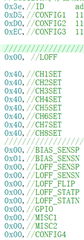
    We've tried it in the non-floating state, and the waveform is the same. The configuration and circuit diagram are attached below, please check whether there is any problem.

    thank you!

  • Hello Jiahao,

    Can you try configuring the device to measure the internal square wave test signal? Set CONFIG2 = 0xD0 and CHnSET to 0x45.

    I also recommend to read through the topics described in our online Bio-potential FAQ. There you will find some helpful debug topics for initial device bring-up and testing.

    Regards,

    Ryan

  • Hello Ryan

    We did an internal square-wave test, and it was okay.

    Are there any problems with the above circuits and configurations?

    thank you!

  • Thanks, Jiahao. This confirms that the ADCs, reference, and SPI communication are working properly. Have you tried applying an external signal from a function generator to one of the channels? Please be sure to describe your test conditions in detail so we can review, if needed.

    Regards,

    Ryan

  • Hello Ryan

    Using the signal generator output waveform test, the waveform collected by the system is correct and consistent with the output waveform of the signal generator.

    The detailed test procedure is as follows: Output 100UV1hz square wave to the EEG system channel with the signal generator. The positive output of the signal generator is connected to the P end of the EEG, and the negative output is connected to the N end, and the right leg driver BIAS is not connected. By reading the original AD value collected by 1299 to describe the waveform, it can be seen that the output waveform is consistent with the signal generator.

    Now I am not sure whether my circuit and configuration are correct, and I hope to get your confirmation.

    Regards,

    Jiahao

  • Hi Jiahao,

    Is there a shared GND connection between the signal generator and the PCB? BIAS is probably not needed for this type of testing, but the GND potential must be common between the two systems. Other than that, I think the setup is correct.

    The data shown in the image above is collected with the same 100µV, 1Hz square wave input signal? It could be that the DC level of the signal is taking some time to settle because there is no shared ground potential. Does it eventually settle?

    Regards,

    Ryan

  • Hello Ryan!

    This signal is picking up the signal that the EEG band picks up on the head, there is no signal generator. The band opens the BIAS, N terminal and P terminal on the head, where the N terminal of the 16 channels is connected together as a reference electrode and the P terminal as a sampling electrode.

    Regards,

    Jiahao

  • When the signal generator is used to output the signal, the collected waveform is consistent with the output waveform of the signal generator, and there is no skew of the waveform.

  • Hi Jiahao,

    The band opens the BIAS, N terminal and P terminal on the head

    I understand that the electrode inputs are connected to the individual P channel inputs and the N channel inputs are all connected to the reference electrode. I think you'll need to check the contact quality of the electrodes on the head, including the BIAS electrode.

    Can you try removing the diodes on the P and N inputs for one channel and compare the drift?

    Regards,

    Ryan

  • Hello Ryan!

    The N-terminal is connected together as a reference electrode, but not connected to SRB1.

    No, because the direction of drift between the channels is not the same, so the test is meaningless.

    Regards,

    Jiahao