This thread has been locked.

If you have a related question, please click the "Ask a related question" button in the top right corner. The newly created question will be automatically linked to this question.

ADS124S08: Wrong lead resistance measurement in three-wire PT100 configuration

Part Number: ADS124S08


Tool/software:

Hello,

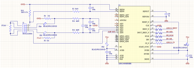
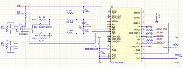
we are trying to read a PT100 RTD with three-wire configuration.

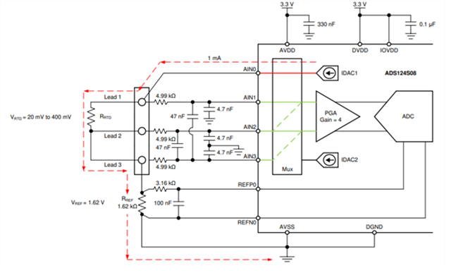
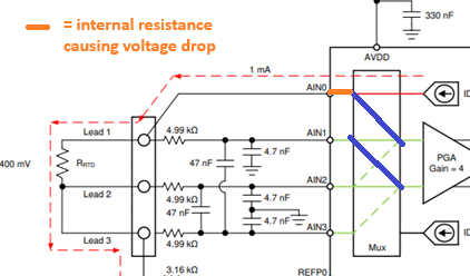
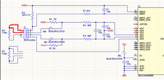
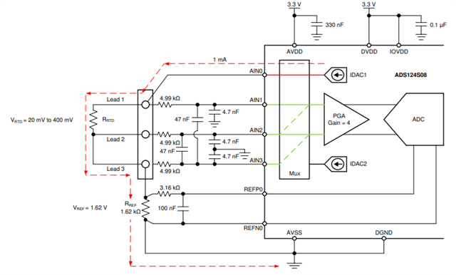
Ou circuit is identical to the one shown in the application note https://www.ti.com/lit/an/sbaa334b/sbaa334b.pdf

We perform measurment in two stages:

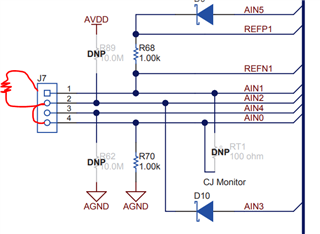
  1. measurement of RTD resistance by activating IDAC1 (1mA) and reading AIN1-AIN2
  2. measurement of LEAD resistance (Rlead2+Rlead3) by activating IDAC1 (1mA) and reading AIN2-AIN3

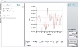
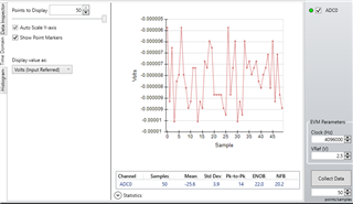
First point (1) gives reasonable output (arount 100Ohms) instead step (2) gives a nonsense result: we aget a voltage drop of about 6mV which corresponds to 6Ohms resistance, which is at least one order of magnitude higher than lead resistance.

Further checks made:

  • Lead resistance is REALLY about 0.6Ohms
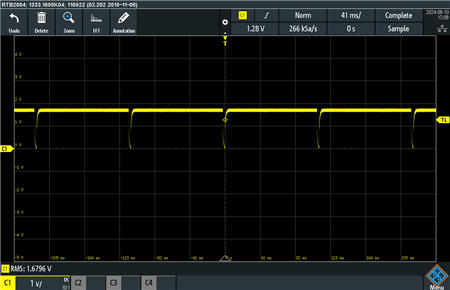
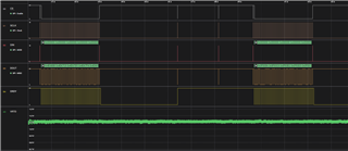
  • Bias current and voltage is correct when read with oscilloscope, despite being very noisy
  • By using an external biasing source, the issue disappears and we get correct reading (around 600uV).

Can you help us?

Thanks,

Marco

  • Hi Marco Barbetta,

    You appear to be performing the correct sequence. Are you changing the gain or the reference source when you change the input mux?

    I assume you are also leaving the IDAC on all the time, correct? In other words, I assume you are not turning the IDAC off and then back on between measurements?

    If you just try reading back the lead resistance multiple times (so don't switch to the main RTD measurement channel), do you get the correct result? Maybe take 100 samples (or 10 seconds, whichever comes first depending on you data rate), and report that back here

    -Bryan

  • Dear Bryan,

    thanks for your suggestions! Please see the answers inline below.

    Marco

    Are you changing the gain or the reference source when you change the input mux?

    >> No we are not.

    I assume you are also leaving the IDAC on all the time, correct? In other words, I assume you are not turning the IDAC off and then back on between measurements?

    >> We can't really do that, the device takes care of everything so the IDAC is switched on and off between measurements (verified with oscilloscope)

    If you just try reading back the lead resistance multiple times (so don't switch to the main RTD measurement channel), do you get the correct result? Maybe take 100 samples (or 10 seconds, whichever comes first depending on you data rate), and report that back here

    >> We tried but the result is the same across the 100 measurements. You can see from the attachment the repeated bias voltage generated by the IDAC.

    Thanks!

  • Hi Marco Barbetta,

    I tried this on my EVM and did not see the error you were mentioning. I used a 500 ohm resistor as the RTD and a 100 ohm resistor as the lead resistance. Applying a 750uA current I read approximately 375mV across the "RTD" and approximately 75mV across the "lead resistance". In the logic analyzer plot below you can see the data on the left side is the RTD measurement (50 samples), then I changed the mux (first AINP = AIN2, then AINN = AIN0), then took another 50x samples.

    I also did not see the current source "dip" as you are showing. I would not have expected this to happen, since you are not changing the IDAC registers after the initialization routine I assume. This is shown in the image below in the signal labeled "VRTD". Note that I have the 500 ohm RTD in series with a 100 ohm and then another 1kohm resistor, so the voltage at this point with respect to ground should be approximately 750uA (500 + 100 + 1000) = 1.2V

    Can you send:

    • Register settings you are using for the initialization
    • Changes to the registers between the RTD and lead resistance measurements
    • Schematic of your system

    -Bryan

  • Dear Bryan,

    I tried this on my EVM and did not see the error you were mentioning. I used a 500 ohm resistor as the RTD and a 100 ohm resistor as the lead resistance. Applying a 750uA current I read approximately 375mV across the "RTD" and approximately 75mV across the "lead resistance". In the logic analyzer plot below you can see the data on the left side is the RTD measurement (50 samples), then I changed the mux (first AINP = AIN2, then AINN = AIN0), then took another 50x samples.

    >> the test conditions are a little difference. Here we are trying to measure a RTD = 100ohm with leads less than 1ohm could please repeat the test in these conditions to see if you find correct measurements?

    I also did not see the current source "dip" as you are showing. I would not have expected this to happen, since you are not changing the IDAC registers after the initialization routine I assume. This is shown in the image below in the signal labeled "VRTD". Note that I have the 500 ohm RTD in series with a 100 ohm and then another 1kohm resistor, so the voltage at this point with respect to ground should be approximately 750uA (500 + 100 + 1000) = 1.2V

    >> we dont' understand how you are able to mantain the Idac on between measurements. In our case, the device automatically turns Idac off after performing the measurement. It is not clear to us whether this is a config of the device or whatever.

    This is our measurement config:

    const struct ads124s08_regs_conf adc_regs_conf = {
        .inpmux = {
            .addr = ADS124S08_REG_INPMUX,
            .val.inpmux.muxp = RTD_ADC_LEAD_PIN0,
            .val.inpmux.muxn = RTD_ADC_PT100_PIN0,
        },
        .pga = {
            .addr = ADS124S08_REG_PGA,
            .val.pga.pga_en = false,
            .val.pga.gain = 1,
        },
        .datarate = {
            .addr = ADS124S08_REG_DATARATE,
            .val.datarate.mode = ADS124S08_MEASURE_MODE_CONTINUOUS,
            .val.datarate.filter = true,
            .val.datarate.dr = ADS124S08_DR_20,
        },
        .ref = { 
            .addr = ADS124S08_REG_REF,
            .val.ref.refp_buf_neg = false,
            .val.ref.refn_buf_neg = true,
            .val.ref.refsel = ADS124S08_REFSEL_P0_N0,
            .val.ref.refcon = ADS124S08_REFCON_ON_AUTO,
    
        },
        .idacmag = {
            .addr = ADS124S08_REG_IDACMAG,
            .val.idacmag.imag = ADS124S08_IMAG_1000_UA,
        },
        .idacmux = {
            .addr = ADS124S08_REG_IDACMUX,
            .val.idacmux.i1mux = ADS124S08_OUTPUT_AIN0,
            .val.idacmux.i2mux = ADS124S08_OUTPUT_DISCONNECTED__,
        },
    };

    and this is a measurement log of the lead (0.6Ohms) resistance measurement, giving approx 7mV result equal to 7Ohms.

    [00:00:25.827,819] <dbg> ads124s08: ads124s08_cmd_send: Sending command 0x02
    [00:00:25.830,230] <dbg> ads124s08: ads124s08_cmd_send: Sending command 0x06
    [00:00:25.832,611] <dbg> ads124s08: ads124s08_reg_write_sequence: Writing to register 0x02 value 0x01
    [00:00:25.832,641] <dbg> ads124s08: ads124s08_reg_write_sequence: Writing to register 0x03 value 0x08
    [00:00:25.832,641] <dbg> ads124s08: ads124s08_reg_write_sequence: Writing to register 0x04 value 0x14
    [00:00:25.832,672] <dbg> ads124s08: ads124s08_reg_write_sequence: Writing to register 0x05 value 0x11
    [00:00:25.832,702] <dbg> ads124s08: ads124s08_reg_write_sequence: Writing to register 0x06 value 0x07
    [00:00:25.832,702] <dbg> ads124s08: ads124s08_reg_write_sequence: Writing to register 0x07 value 0xF0
    [00:00:25.833,007] <dbg> ads124s08: ads124s08_reg_read_sequence: Read from register 0x02 value 0x01
    [00:00:25.833,007] <dbg> ads124s08: ads124s08_reg_read_sequence: Read from register 0x03 value 0x08
    [00:00:25.833,038] <dbg> ads124s08: ads124s08_reg_read_sequence: Read from register 0x04 value 0x14
    [00:00:25.833,068] <dbg> ads124s08: ads124s08_reg_read_sequence: Read from register 0x05 value 0x11
    [00:00:25.833,068] <dbg> ads124s08: ads124s08_reg_read_sequence: Read from register 0x06 value 0x07
    [00:00:25.833,099] <dbg> ads124s08: ads124s08_reg_read_sequence: Read from register 0x07 value 0xF0
    [00:00:25.833,129] <dbg> ads124s08: ads124s08_cmd_send: Sending command 0x08
    [00:00:25.939,910] <inf> ads124s08: buffer1: 008dbb
    [00:00:25.939,941] <dbg> ads124s08: ads124s08_read_measure: reading measure with value 36283
    [00:00:25.939,971] <dbg> ads124s08: ads124s08_cmd_send: Sending command 0x0A
    [00:00:25.940,032] <dbg> ads124s08: ads124s08_cmd_send: Sending command 0x04
    [00:00:25.940,124] <inf> rtd: lead0 uv 7006

    and here is the schematic

    thanks for any help you can give us.

    Marco

  • Hi Marco Barbetta,

    The tests I ran were just to mimic what you are doing, not recreate it exactly. I just wanted to be able to show that the ADC can swap back and forth between the two measurements, read them correctly using the internal IDAC, and that the IDAC does not turn off between measurements.

    • Your code shows "Writing to register 0x02 value 0x01", which sets MUXP = AIN0 and MUXN = AIN1. However, your schematic shows that this is not where the lead resistance measurement would be. Am I missing something?
    • You code shows "Writing to register 0x03 value 0x08", which turns on the PGA and sets the gain to 1. However, your initialization routine set PGA_EN = false, which I assume means the PGA is off. Why are you changing this?
    • I am not sure why you are rewriting the IDAC measurement to measure the lead resistance (again, I cannot see your full code flow so maybe you only do this once?) But you've already set this register initially, not sure why you need to send it again (I guess because you issue a RESET command, but also why?)
    • You mentioned a 3-wire RTD with two measurements, however you are showing a 4-wire RTD in your schematic. I just want to be clear what you are measuring
    • Where does "AMP_OUT" go? You assign the IDAC output to AIN0 in your code, but I cannot see where this net goes.
    • You are issuing the POWERDOWN command (0x04), which would explain why the IDAC is turning off. Since I cannot see you code flow, it's not clear when / how often you issue this command. If you change the REFCON bits to 10b, the VREF (and therefore the IDAC) will stay on in PWDN mode

    -Bryan

  • Dear Bryan,

    thanks.

    Please see the answers inline below.

    • Your code shows "Writing to register 0x02 value 0x01", which sets MUXP = AIN0 and MUXN = AIN1. However, your schematic shows that this is not where the lead resistance measurement would be. Am I missing something?

    >> Sorry for that, the schematic is referred to an updated version of the board which was not yet prototyped. Please find here the correct one.

    • You code shows "Writing to register 0x03 value 0x08", which turns on the PGA and sets the gain to 1. However, your initialization routine set PGA_EN = false, which I assume means the PGA is off. Why are you changing this?

    >> You were right. So we set the PGA always off.

    • I am not sure why you are rewriting the IDAC measurement to measure the lead resistance (again, I cannot see your full code flow so maybe you only do this once?) But you've already set this register initially, not sure why you need to send it again (I guess because you issue a RESET command, but also why?)

    >> We removed this part and just leave the IDAC always on without changing settings. We verified with oscilloscope that now we see no drop of bias voltage between measurements.

    • You mentioned a 3-wire RTD with two measurements, however you are showing a 4-wire RTD in your schematic. I just want to be clear what you are measuring

    >> Again you are right, the updated schematic describes the real case we are tesiting.

    • Where does "AMP_OUT" go? You assign the IDAC output to AIN0 in your code, but I cannot see where this net goes.

    >> This is just an auxiliary imput for other purposes.

    • You are issuing the POWERDOWN command (0x04), which would explain why the IDAC is turning off. Since I cannot see you code flow, it's not clear when / how often you issue this command. If you change the REFCON bits to 10b, the VREF (and therefore the IDAC) will stay on in PWDN mode

    >> We removed this part and just leave the IDAC and VREF always on without changing settings. We verified with oscilloscope that now we see no drop of bias voltage between measurements.

    Please find the updated log which are consequence the aforemetioned changes.

    ads124s08: ads124s08_cmd_send: Sending command 0x02
    ads124s08: ads124s08_cmd_send: Sending command 0x06
    ads124s08: ads124s08_reg_write_sequence: Writing to register 0x02 value 0x01
    ads124s08: ads124s08_reg_write_sequence: Writing to register 0x03 value 0x00
    ads124s08: ads124s08_reg_write_sequence: Writing to register 0x04 value 0x14
    ads124s08: ads124s08_reg_write_sequence: Writing to register 0x05 value 0x12
    ads124s08: ads124s08_reg_write_sequence: Writing to register 0x06 value 0x07
    ads124s08: ads124s08_reg_write_sequence: Writing to register 0x07 value 0xF0
    ads124s08: ads124s08_reg_read_sequence: Read from register 0x02 value 0x01
    ads124s08: ads124s08_reg_read_sequence: Read from register 0x03 value 0x00
    ads124s08: ads124s08_reg_read_sequence: Read from register 0x04 value 0x14
    ads124s08: ads124s08_reg_read_sequence: Read from register 0x05 value 0x12
    ads124s08: ads124s08_reg_read_sequence: Read from register 0x06 value 0x07
    ads124s08: ads124s08_reg_read_sequence: Read from register 0x07 value 0xF0
    ads124s08: ads124s08_cmd_send: Sending command 0x08
    ads124s08: buffer1: 00c670
    ads124s08: ads124s08_read_measure: reading measure with value 50800
    ads124s08: buffer1: 00c670
    ads124s08: ads124s08_read_measure: reading measure with value 50800
    ads124s08: buffer1: 00c63b
    ads124s08: ads124s08_read_measure: reading measure with value 50747
    ads124s08: buffer1: 00c63b
    ads124s08: ads124s08_read_measure: reading measure with value 50747
    ads124s08: buffer1: 00c63b
    ads124s08: ads124s08_read_measure: reading measure with value 50747

    The issue is still there, we measure several millivolts where we should measure a pure short. Did you have the chance to test your setup with a pure short?

    Thanks,

    Marco

  • Hi Marco Barbetta,

    Using the ADS124S08EVM (schematic shown below), I connected a 100ohm resistor between J7-1 and J7-2, then connected a short wire between J7-2 and J7-4 as shown. Then I took separate measurements between AIN1/AIN2 (the "RTD") and AIN2/AIN0 (the "lead resistance") using 1mA current source.

    You can see my results below, where I measured ~100mV for the "RTD" and ~0V for the "lead resistance". So yes this is definitely achievable with the ADS124S08 using the configuration you have. I am not sure what else could be wrong, this is a relatively simple circuit

    Can you try:

    1. Removing the 1Mohm pull-up/pull-down resistors and see if the situation improves
    2. Using the internal reference as the reference source instead of the reference resistor
    3. Removing the RTD and use a fixed value resistor in its place e.g. 100ohm, like I did. Use a wire for a short.
    4. Disconnecting everything from J2 and just short the lead resistance channels together using a wire (looks to be J2-3 and J2-4 in your system). See if you can measure ~0V

    Please report back the results of these experiments

    "RTD"

    "lead resistance"

    -Bryan

  • Dear Bryan,

    thanks for your further suggestions.

    1. Removing the 1Mohm pull-up/pull-down resistors and see if the situation improves
    2. Using the internal reference as the reference source instead of the reference resistor
    3. Removing the RTD and use a fixed value resistor in its place e.g. 100ohm, like I did. Use a wire for a short.
    4. Disconnecting everything from J2 and just short the lead resistance channels together using a wire (looks to be J2-3 and J2-4 in your system). See if you can measure ~0V

    unfortunately, none of those solved the issue. Also, we tried to measure a known reaistance value, seeing an error of some Ohms/mV.

    So we tried SELFOCAL but the 8-10mV delta debween channels is still there.

    So my conclusion is that the unit has to be faulty. Maybe for an excessive soldering temperature during prototyping.

    So we are building a new prototype and we will retest and get back here with an update.

    Thanks

    Marco

  • Hi Marco Barbetta,

    Did any of those things actually work? They weren't all intended to solve the issue, some were just to see how the ADC responds. For example, #4 was just to measure the ADC noise and see if it correlated to the datasheet noise (which is probably should have, since the ADC and PGA appear to be okay if you are getting correct results on at least one channel). This at least tells you that the mux is working properly

    It would be helpful to see the results of these tests just in case getting a new unit does not solve the issue

    -Bryan

  • Dear Bryan,

    I think we figured out at last.

    We replaced the part and we measured almost ZERO between lead 2 and lead 3. Which is correct. So the other one must have been damaged.

    Then, we tried the other measurement: between AIN0 and AIN1 with IDAC ON. Still 9 mV.

    So we switched off the IDAC and provided a fixed external bias to Lead 1. Now ZERO mV.

    My conclusion is that it is not allowed to use IDAC and ADC input at the same time at the same input, due to the MUX resistance which will cause a voltage drop. In other words, we were measuring port series resistance resistance.

    Can you confirm this?

    Thanks,

    Marco

  • Hi Marco Barbetta,

    I am confused by the drawing you just provided. The lead resistance measurement in that image is between AIN2 and AIN3, not AIN0 and AIN1. Measuring between AIN0 and AIN1 would measure the trace/mux resistance (as you have identified), as well as any additional resistance between AIN0 and the terminal block connected to Lead 1

    I believe I mentioned this in my previous post:

    Your code shows "Writing to register 0x02 value 0x01", which sets MUXP = AIN0 and MUXN = AIN1. However, your schematic shows that this is not where the lead resistance measurement would be. Am I missing something?

    According to your most recent schematic, it doesn't seem like you are actually able to measure the lead resistance because you cannot use REFP0 as an analog input (you could use REFP1 however). I highlighted the lead resistance measurement path in red

    -Bryan