This thread has been locked.

If you have a related question, please click the "Ask a related question" button in the top right corner. The newly created question will be automatically linked to this question.

ADS1299EEGFE-PDK:ADS1299EEGFE-PDK

Part Number: ADS1299EEGFE-PDK
Other Parts Discussed in Thread: ADS1299
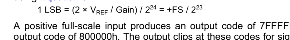
Tool/software:

Hi,

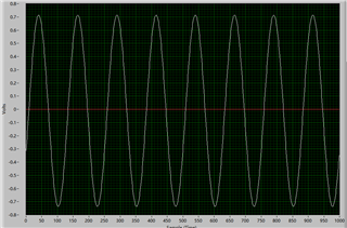
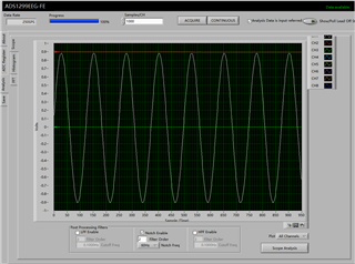
I used channel 1 of ADS1299 to test a sine function I generated myself. The frequency of the sine function was 2Hz and the amplitude was 0.3Vrms. The waveform I saw in the ADS1299 GUI was the white waveform. The strange thing was that its maximum value was about 0.9V. I wanted to know why this was because the PGA gain of my channel 1 was 1, without any amplification.

Regards,

Junzhe

  • Hello Junzhe,

    Is the sine wave single-ended or differential? Can you probe the IN1P and IN1N pins to confirm the output of the signal generator is as expected? 

    Also, does your function generator have an output impedance setting which you can adjust? Make sure that it is set to High-Z output and not 50-ohm termination.

    Regards,

    Ryan

  • Hi Ryan,

    I seem to have fixed the problem through debugging, but there is still an offset in the signal I get.

    My sine wave is a single-ended input, connected to CH1+, CH1- is connected to the AGND of ADS1299 and the negative output of the function generator. I selected the High-Z output and I confirmed that the function generator was working properly. The figure shows the waveform I measured. The waveform sent by my function generator is a sine wave with a Vrms of 0.5 and a 2Hz frequency. The gain of channel 1 of ADS1299 is set to 2, so I think the maximum and minimum values ​​of the measured waveform should be 1414mV.

    This is my code for converting the Hex value to mV voltage, I feel like there is nothing wrong with it, but I am unclear as to why this offset is occurring.

    Regards

    Junzhe

  • In addition, I am a little confused about the function of PGA. I input the same signal, but use the "analysis" in TI's GUI to analyze it, and the resulting sine wave is not amplified, but the gain I set at this time is 2. I only use CH1.

  • Hi Junzhe - do you have the checkbox marked for "Analysis data is input-referred"?

    Regards,

    Ryan

  • Yes, I choose it.

    Regards

    Junzhe

  • Hi Ryan,

    I think it may be due to the Gain in this formula. When the gain of the channel is changed, the value of LSB will also change. In my design, I calculated the LSB corresponding to Gain of 1, which I called Voltage_Scale1 in the code. When I changed the channel gain, this value remained unchanged, so I could get the correct waveform, but there was a certain offset, and I didn't know the reason for the offset. However, in the TI GUI code, the design code at that time may have been written according to this gain formula, so when the gain of the channel was changed, the corresponding LSB value kept changing and getting smaller, which caused the increase in the channel gain and the decrease in the LSB to cancel each other out, so the changes brought about by the change in PGA could not be reflected.

    Regards 

    Junzhe

  • Hi Ryan,

     I still waiting for your help for this question.

    Regards

    Junzhe

  • Hi Junzhe,

    The GUI is displaying the input-referred data. This means that it is automatically accounting for the PGA gain by adjusting the LSB size according to the formula above. You can uncheck this option if you want to see voltage scale with PGA gain.

    Regards,

    Ryan